Method of stereoscopic 3D viewing using wireless or multiple protocol capable shutter glasses

a technology of shutter glasses and stereoscopic 3d, applied in the field of stereoscopic 3d image viewing methods and apparatus, can solve the problems of system response to expensive silver or metalized reflective screens, system limited use in darkened environments, and screen is often too expensive for the average consumer, so as to simplify the user experience of wearing stereoscopic glasses, improve and increase the level of synchronization

Inactive Publication Date: 2010-08-05
BIT CAULDRON CORP
View PDF14 Cites 183 Cited by
  • Summary
  • Abstract
  • Description
  • Claims
  • Application Information

AI Technical Summary

Benefits of technology

[0020]In various embodiments of the present invention, a stereoscopic 3D image viewing device is based upon liquid crystal display (LCD) shutters that are synchronized to a source of 3D images. In various embodiments, the synchronization is based upon rf protocols such as Bluetooth, ZigBee radio (ZigBee Alliance), IEEE Standard 802.15.1, IEEE Standard 802.15.4, or any other type of rf communications protocol. In some embodiments of the present invention, the stereoscopic 3D image viewing device may transmit data back to the source of 3D images, via the rf communications mechanism or protocol, to increase the level of synchronization between the two devices.
[0021]In various embodiments, by using a multitude of communications protocols (e.g. rf) and adding feedback from 3D shutter glasses back to the 3D image source, a system, method, and apparatus of perceiving stereoscopic 3D can be generated which improves the level of synchronization between the alternating images and the alternating action of shutter glasses. A system, apparatus, method, and computer-readable media are provided to enable stereoscopic viewing. In particular, according to one method, the physical method of connecting the display system to stereoscopic glasses is the IEEE 802.15.4 wireless radio, ZigBee radio or Bluetooth technology. This allows a user to move one's head into positions that would normally lose reception of wireless transmissions (e.g. IR) thus simplifying the user experience of wearing stereoscopic glasses. The wireless radio connection also has the advantage of replacing the infra-red light transmission method and its associated interference with remote controls and tendency to accept interference from natural and artificial light sources, thus enhancing the user experience.

Problems solved by technology

One such drawback includes that such systems typically rely upon images provided by a light projector and thus such systems are limited for use in darkened environments.
Another drawback includes that such systems typically reply upon expensive silver or metalized reflective screens, that maintain the appropriate polarization of light from the projector to the right and left eye images.
Such screens are often too expensive for the average consumer.
Yet another drawback is that because both left and right eye images are displayed to the user at the same time, despite the polarized glasses, right eye images are often visible to the left eye and left eye images are often visible to the right eye.
This light pollution degrades the quality of the 3D images and can be termed as “ghosting” of 3D images.
The inventors believe that such techniques are disadvantageous as they tend to reduce the contrast of objects in an image, and they may result in a visible halo around objects in the image.
As a result of using these circular or linear polarized glasses, the inventors have recognized that 3D versions of features often do not appear as aesthetically pleasing as 2D versions of such features.
Because of these different data formats, IR transmitters from one manufacturer often cannot be used with LCD glasses from another manufacturer.
However, in practice, then inventors have determined that there are many limitations that degrade the performance of such systems and that limit the applicability of such systems from being successfully and widely adopted.
One such limitation includes the difficulty in synchronizing the glasses to the images that are displayed.
As a result of such latency and jitter information, the LCD lenses or shutters are often opened and closed often at improper times, e.g. out of phase, with some of the image intended for the left eye being shown to the right eye and vice versa.
Additionally, as the inventors have determined that the phase difference is not constant and is subject to jitter, the user may see the image brightness change or flicker undesirably.
One such drawback is the reduction in net amount of light transmitted to the user's eyes.
Another limitation is the use of the IR communications channel itself.
Additionally, it has been observed by the inventors that IR LCD Glasses may also lose synchronization as a result of clothing, hair, portions of other users bodies (e.g. head), or the like, that temporarily obscure an IR receiver of the LCD glasses.
The inventors believe such a solution limits the applicability and attractiveness of such 3D display devices to typical consumers.
This is believed to be because most consumers do not have the luxury of a dedicated, light-controlled room for a home theater, and that most consumer entertainment rooms are multipurpose family rooms.
An additional drawback to such devices, determined by the inventors, is that multiple 3D display systems cannot easily be operated in the vicinity of each other.
Because of this, although a user is viewing a first 3D display, the user's 3D glasses may be synchronizing to a different 3D display, causing the user to undesirably view flickering and rolling images.

Method used


Image

  • Method of stereoscopic 3D viewing using wireless or multiple protocol capable shutter glasses
  • Method of stereoscopic 3D viewing using wireless or multiple protocol capable shutter glasses
  • Method of stereoscopic 3D viewing using wireless or multiple protocol capable shutter glasses

Examples


Embodiment Construction

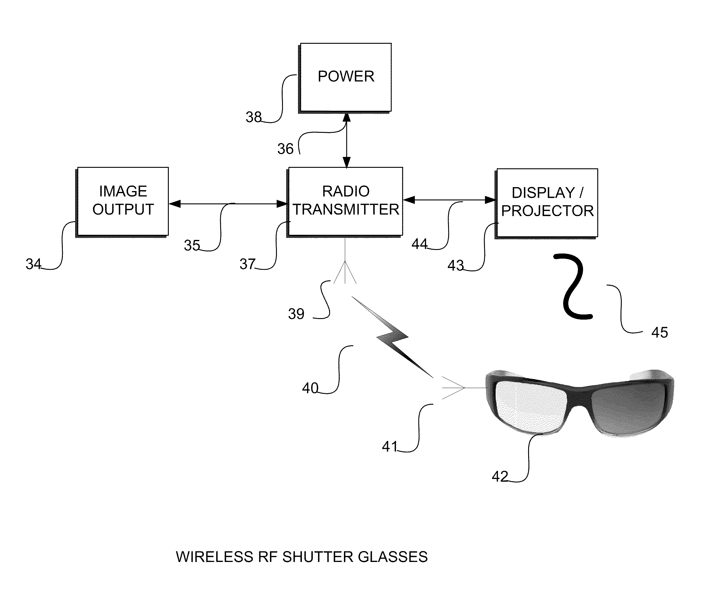
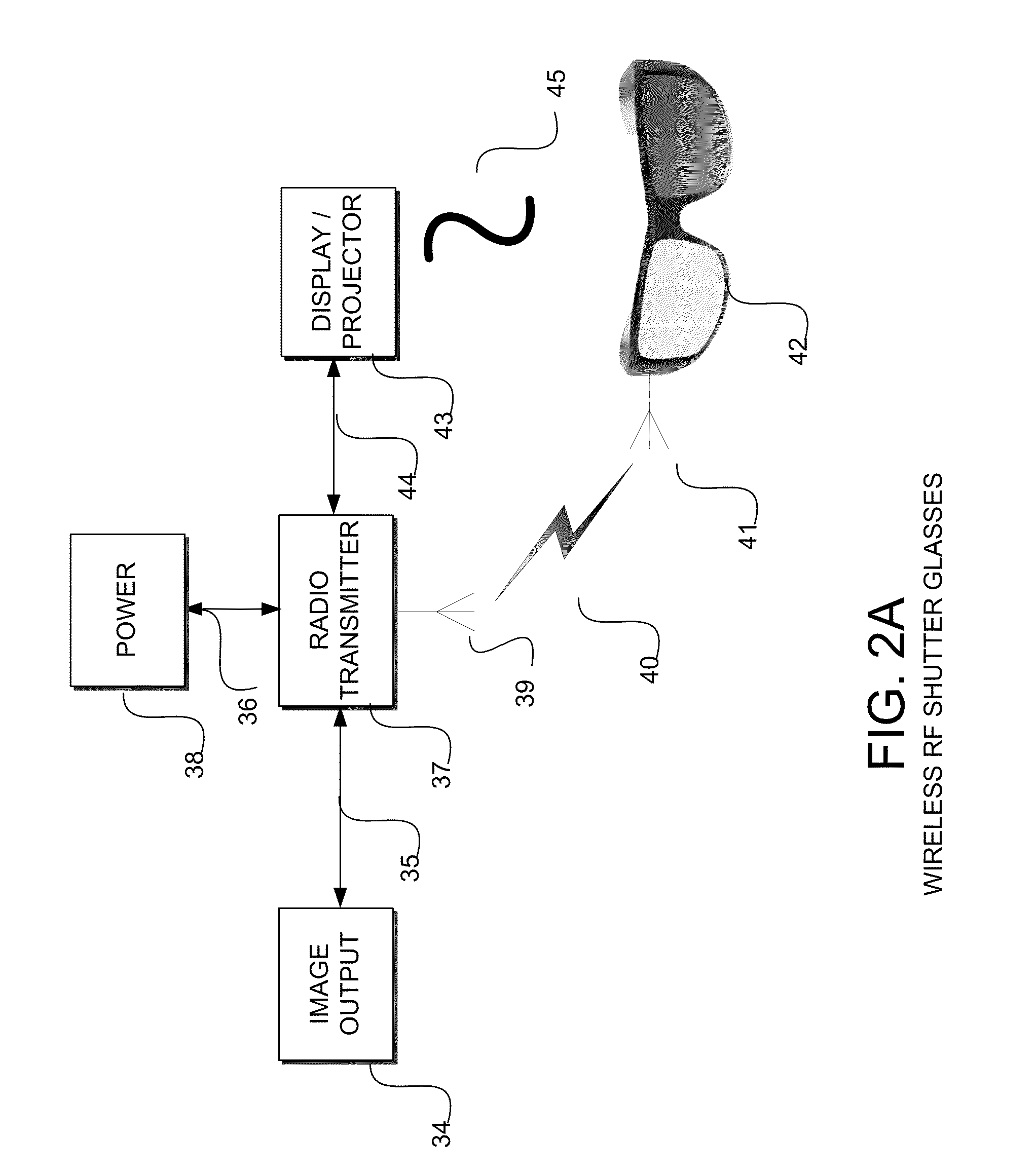
[0058]FIGS. 2A-D illustrate various embodiments of the present invention. In particular, FIGS. 2A-D illustrate various arrangements of embodiments of the present invention.

[0059]FIG. 2A includes a 3D source 34 of image data, a transmission device 37, a display 43, and shutter glasses 42. In various embodiments, 3D source 34 may be a computer, a Blu-ray or DVD player, a gaming console, a portable media player, set-top-box, home theater system, preamplifier, a graphics card of a computer, a cable box, or the like, and 3D display 43 may be any 3D display device such as an LCD / Plasma / OLED display, a DLP display, a projection display, or the like. In various embodiments, transmission device 37 and shutter glasses 42 may be embodied by a product developed by the assignee of the current patent application, Bit Cauldron Corporation of Gainesville, Fla. In some embodiments, shutter glasses 42 may be implemented with mechanical shutters or LCD shutters. For example, LCD shutters based upon pi...


PUM


Abstract

A system, apparatus, method, and computer-readable media are provided for the viewing of stereoscopic three dimensional (3D) images using shutter glasses. According to one method, a wireless protocol is used to communicate stereoscopic synchronization information. The glasses may scan wireless, infrared, and visible light signals to deduce the timing necessary for stereoscopic synchronization with the display. The necessary synchronization information is then determined from the information in these signals. Other methods incorporate this technology into a mobile device, a cradle or dongle that attaches to the mobile device, or an otherwise ordinary pair of sunglasses.

Description

CROSS-REFERENCES TO RELATED APPLICATIONS[0001]The present patent application claims priority to provisional application Nos. 61 / 149,651 filed Feb. 3, 2009, 61 / 149,666 filed Feb. 3, 2009, 61 / 251,739 filed Oct. 15, 2009, 61 / 182,845 filed Jun. 1, 2009, titled “Method Of Stereoscopic Synchronization Of Active Shutter Glasses,” 61 / 218,069 filed Jun. 18, 2009, titled “System And Method Of Transmitting And Decoding Stereoscopic Sequence Information,” 61 / 251,739 filed Oct. 15, 2009, titled “System And Method For Displaying 3D Using Crystal Sweep With Freeze Tag,” and 61 / 300,961 filed Feb. 3, 2010, titled “Methods And Apparatus Of Tuning Active Shutter Glasses For Operation With An Arbitrary Display.” The present invention also relates to co-pending U.S. Pat. No. ______ filed Feb. 3, 2010, titled “Method Of Stereoscopic 3D Image Capture Using A Mobile Device, Cradle Or Dongle,” Attorney docket No. 028319-000110US. These disclosures are herein by incorporated by reference, for all purposes.BA...

Claims


Application Information

Patent Timeline
Patent Type & Authority Applications(United States)
IPC IPC(8): H04N13/04H04N13/00
CPCG02B27/2264G09G3/003H04N2213/008H04N13/0438G09G2310/08G02B30/24H04N13/341
Inventor MENTZ, JAMESCALDWELL, SAMUEL
Owner BIT CAULDRON CORP
Why Eureka
Try Eureka