One such drawback includes that such systems typically rely upon images provided by a light
projector and thus such systems are limited for use in darkened environments.
Another drawback includes that such systems typically reply upon expensive silver or metalized reflective screens, that maintain the appropriate polarization of light from the
projector to the right and
left eye images.
Such screens are often too expensive for the average
consumer.
Additional drawbacks include that both left and right eye images are displayed to the user at the same time and polarizers are often imperfect, further, light can change polarization when it reflects off a screen, accordingly, despite the polarized glasses, right eye images are often visible to the
left eye and
left eye images are often visible to the right eye.
The inventors believe that such techniques are disadvantageous as they tend to reduce the contrast of objects in an image, and they may result in a visible halo around objects in the image.
As a result of using these circular or linear polarized glasses, the inventors have recognized that 3D versions of features often do not appear as aesthetically pleasing as 2D versions of such features.
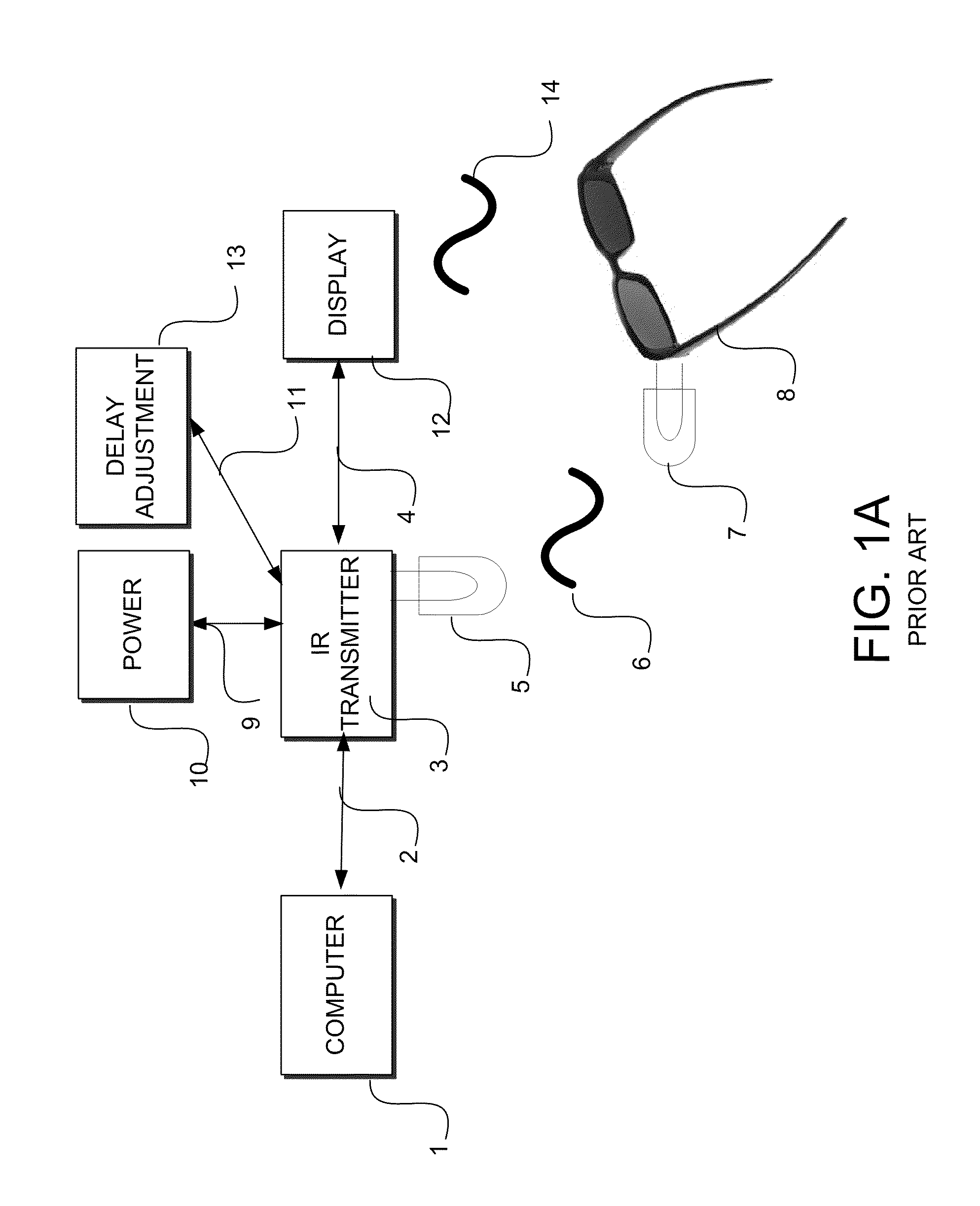
Because of these different data formats, IR transmitters from one manufacturer often cannot be used with LCD glasses from another manufacturer.
However, in practice, then inventors have determined that there are many limitations that degrade the performance of such systems and that limit the applicability of such systems from being successfully and widely adopted.
One such limitation includes the difficulty in
synchronizing the glasses to the images that are displayed.
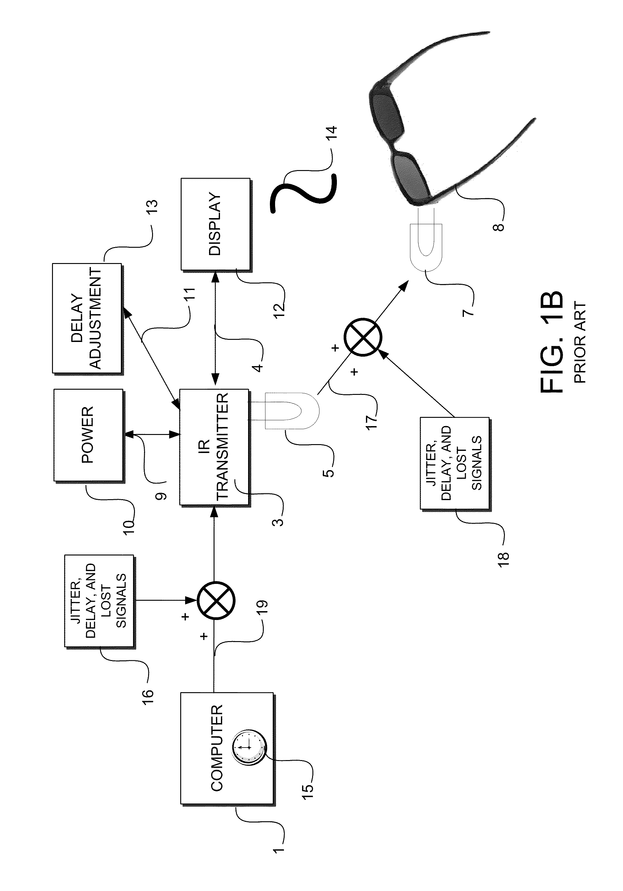
As a result of such latency and
jitter information, the LCD lenses or shutters are often opened and closed often at improper times, e.g.
out of phase, with some of the image intended for the left eye being shown to the right eye and vice versa.
Additionally, as the inventors have determined that the
phase difference is not constant and is subject to
jitter, the user may see the image brightness change or
flicker undesirably.
Because these disturbances are random, it is impossible for
delay adjustment 13 to properly compensate or account for the disturbances.
This jittering may
delay the time 21 when the right-eye shutter should be opened (shortening the amount of time the right-eye image is viewed causing a darker right-eye image) or may cause the right-eye shutter to open too early (when a left-eye image is being displayed, causing a
ghosting effect).
As can be seen in this example, the random jittering may reduce the viewer's enjoyment in watching 3D images.
One such drawback is the reduction in net amount of light transmitted to the user's eyes.
Another limitation is the use of the IR communications channel itself.
Additionally, it has been observed by the inventors that IR LCD Glasses may also lose synchronization as a result of clothing, hair, portions of other users bodies (e.g. head), or the like, that temporarily obscure an IR
receiver of the LCD glasses.
The inventors believe such a solution limits the applicability and attractiveness of such 3D display devices to typical consumers.
This is believed to be because most consumers do not have the luxury of a dedicated, light-controlled room for a home theater, and that most
consumer entertainment rooms are multipurpose family rooms.
An additional drawback to such devices, determined by the inventors, is that multiple 3D display systems cannot easily be operated in the vicinity of each other.
Because of this, although a user is viewing a first 3D display, the user's 3D glasses may be
synchronizing to a different 3D display, causing the user to undesirably view flickering and rolling images.
An additional drawback to conventional 3D shutter glasses includes the real-world introduction of latency and
jitter into the
system.
Such uncorrelated latency and jitter typically affects the synchronization information as it is transmitted to the 3D shutter glasses and the electrical or electromechanical shutters of the 3D glasses as they are actuated.
The
perception of this phase discrepancy is commonly called
ghosting and causes the images to jitter, causes changes in perceived brightness of the images, and / or causes disruptive flickering of the images.

