Eureka AIR delivers breakthrough ideas for toughest innovation challenges, trusted by R&D personnel around the world.

Optical member, lighting device for display device, display device and television receiver

a technology for lighting devices and optical components, which is applied in the direction of illuminated signs, display means, instruments, etc., can solve the problems of inability to compensate for luminance reduction, and achieve the effect of improving light diffuseness and light use efficiency, and high luminan

Active Publication Date: 2010-08-05
SHARP KK
View PDF2 Cites 2 Cited by
  • Summary
  • Abstract
  • Description
  • Claims
  • Application Information

AI Technical Summary

Benefits of technology

[0005]The present invention was made in view of the foregoing circumstances, and an object thereof is to provide an optical member that can offer high luminance in both light guiding direction and non-light-guiding direction of the lenses and improve the light diffuseness and the light use efficiency. Another object of the present invention is to provide a display device having such a lighting device for a display device and a television receiver having such a display device.Means for Solving the Problem
[0007]According to such an optical member, the diffuseness of the light diffusing sheet has anisotropy, that is, the diffuseness is larger in the light guiding direction of the lens sheet than in the non-light-guiding direction. This resolves the problem that luminance in a direction diagonal to the light guiding direction is lower than in the non-light-guiding direction. Namely, the known light diffusing sheet has isotropic diffuseness and thus it cannot compensate for the luminance reduction in a certain direction (light guiding direction) on the lens sheet. By providing the light diffusing sheet having anisotropic diffuseness as in the present invention, the luminance reduction in a certain direction (light guiding direction) on the lens sheet can be compensated. Further, the diffuseness and the light use efficiency can be improved at the same level as before and the optical member that can offer high luminance in both light guiding direction and non-light-guiding direction of the lenses can be provided.

Problems solved by technology

Namely, the known light diffusing sheet has isotropic diffuseness and thus it cannot compensate for the luminance reduction in a certain direction (light guiding direction) on the lens sheet.

Method used


Image

  • Optical member, lighting device for display device, display device and television receiver
  • Optical member, lighting device for display device, display device and television receiver
  • Optical member, lighting device for display device, display device and television receiver

Examples


Embodiment Construction

[0020]An embodiment of the present invention will be explained with reference to drawings.

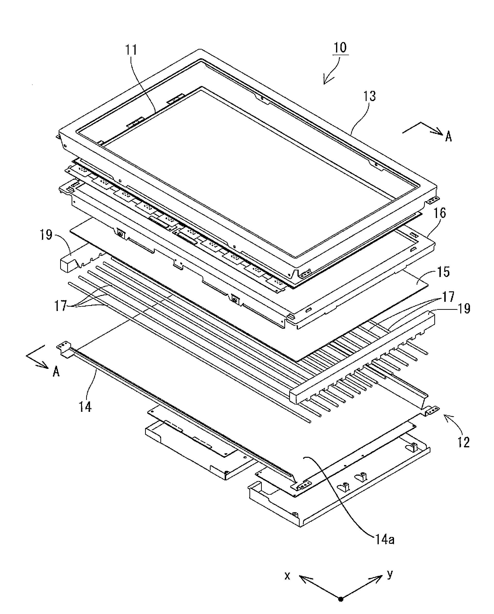
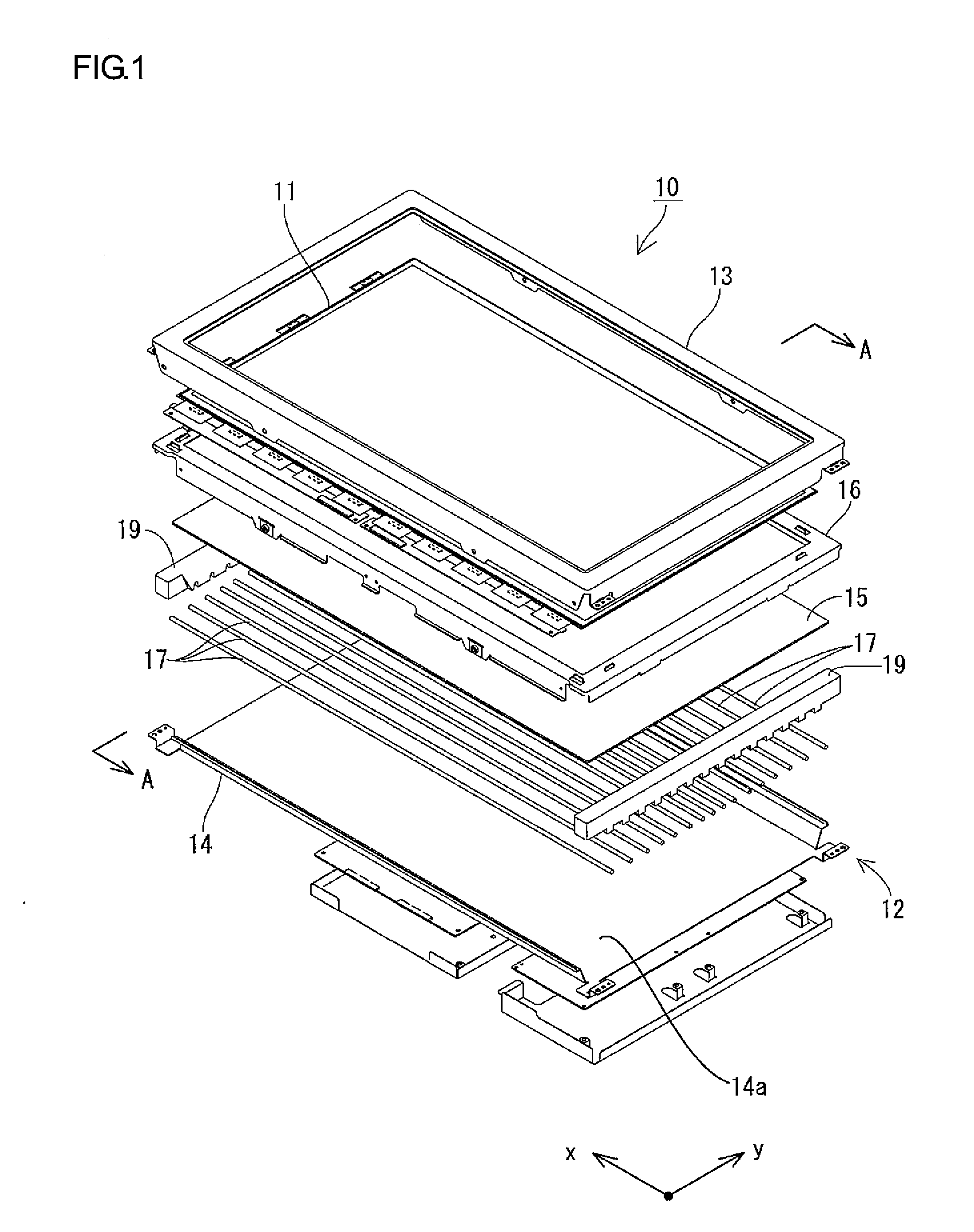
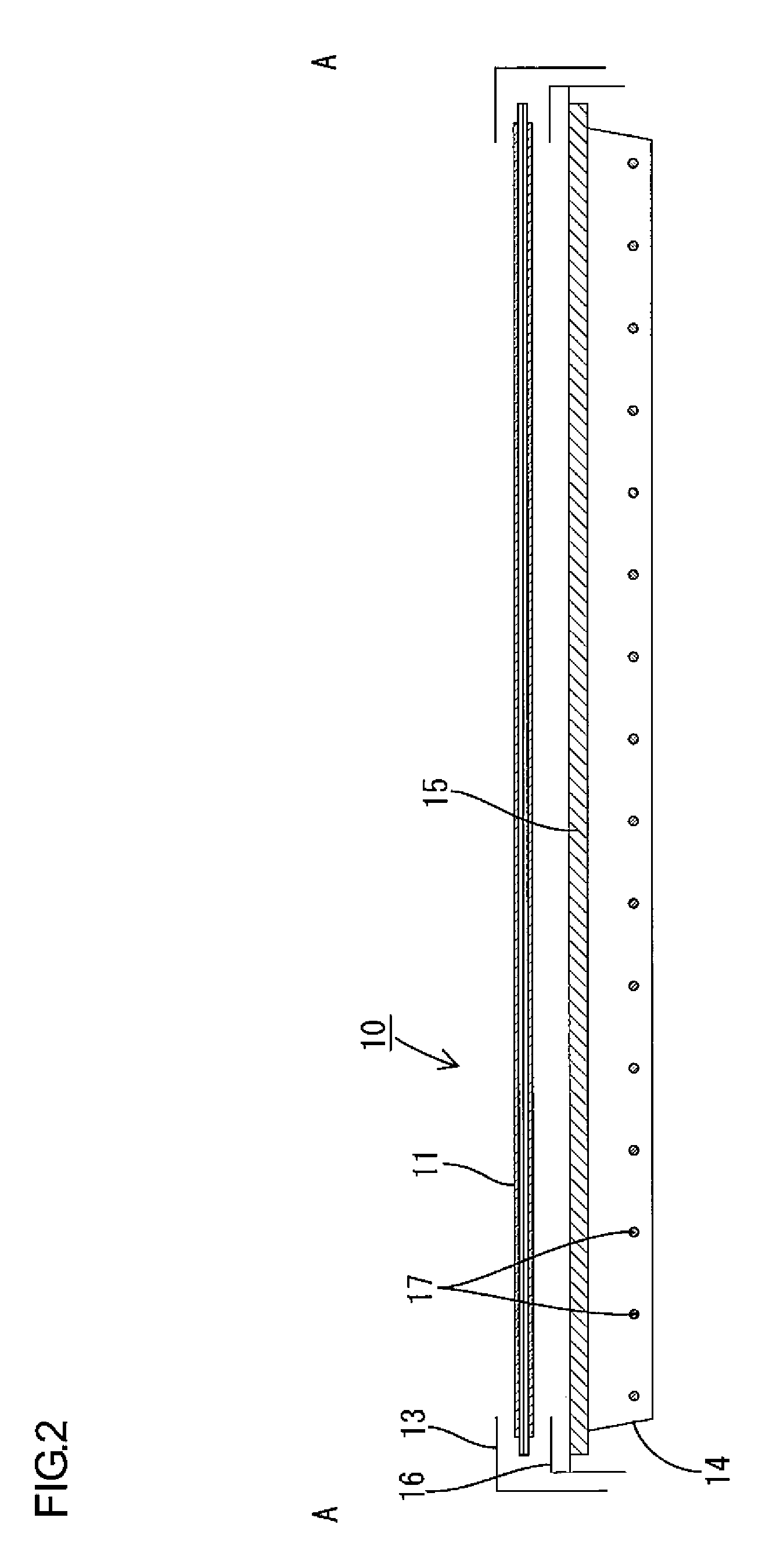
[0021]FIG. 1 is an exploded perspective view illustrating the general construction of a liquid crystal display device (display device) 10 of the present embodiment. FIG. 2 is a cross-sectional view of FIG. 1 along the line A-A. FIG. 3 is a perspective view of an embodiment of a television receiver using the liquid crystal display device 10. FIG. 4 is a perspective view illustrating the general construction of an optical member 15 included in the liquid crystal device 10. FIG. 5 is a cross-sectional view illustrating a construction of FIG. 4 along the line B-B. FIG. 6 is a schematic view illustrating a construction of a light diffusing sheet 27 included in the optical member 15. An x-axis and a y-axis are shown in some drawings to indicate orientations of the illustrations.

[0022]First, a general configuration of the liquid crystal display device (display device) 10 will be explained.

[0023]As ill...


PUM

PropertyMeasurementUnit
anisotropyaaaaaaaaaa
areaaaaaaaaaaa
light diffusion angleaaaaaaaaaa

Abstract

An optical member 15 of the present invention includes a lens sheet 28, a light diffusing sheet 27 and light reflecting members 24. The lens sheet 28 has a plurality of convex lenses 29 on an inner surface thereof. The light diffusing sheet 27 is disposed so as to face the lens sheet 28 and diffuses light. The light reflecting members 24 are selectively arranged in boundary areas of the plurality of convex lenses 29 between the lens sheet 28 and the light diffusing sheet 27. The lens sheet 28 has a surface having a light guiding direction and a non-light-guiding direction that crosses the light guiding direction because the convex lenses 29 have anisotropy for collecting light. The light diffusing sheet 27 has diffuseness larger in the light guiding direction of the lens sheet 28 than in the non-light-guiding direction of the lens sheet 28.

Description

TECHNICAL FIELD[0001]The present invention relates to an optical member, a lighting device for a display device, a display device and a television receiver.BACKGROUND ART[0002]A liquid crystal display device generally includes a liquid crystal panel that is a display panel and a backlight unit that is an external light source disposed behind the liquid crystal panel. The backlight unit includes a plurality of cold cathode tubes that are linear light sources, and an optical member for converting light emitted from each cold cathode tubes to even planar light. An example configuration of the optical member is disclosed in Patent Document 1.Patent Document 1: JP-A-2005-221619 Problem to be Solved by the Invention[0003]The optical member disclosed in Patent Document 1 includes a lens portion having a plurality of cylindrical lenses arranged on one surface and a reflection layer having an opening on the other surface. Diffuser plates are arranged so as to sandwich the lens portion and t...

Claims


Application Information

Patent Timeline
Patent Type & Authority Applications(United States)
IPC IPC(8): G02F1/13357G02B5/02
CPCG02B3/06G02B5/02G02F2001/133607G02F1/133606G02F1/133604G02F1/133607
Inventor TAKATA, YOSHIKI
Owner SHARP KK
Why Eureka
Eureka Blog
Learn More