Methods and systems for heating transmission fluid

a transmission fluid and transmission fluid technology, applied in the direction of gear lubrication/cooling, gearing control, gearing elements, etc., can solve the problems of engine friction, differential spin loss, engine and differential spin loss, etc., to reduce noise, reduce exhaust emissions, and save fuel

Active Publication Date: 2010-08-05
FORD GLOBAL TECH LLC
View PDF11 Cites 31 Cited by
  • Summary
  • Abstract
  • Description
  • Claims
  • Application Information

AI Technical Summary

Benefits of technology

[0002]Vehicles have been developed to perform an idle-stop when idle-stop conditions are met and automatically restart the engine when restart conditions are met. Such idle-stop systems enable fuel savings, reduction in exhaust emissions, reduction in noise, and the like. As such, a number of methods may be used to control the hydraulically operated transmission to improve idle-stops and subsequent restarts, when restart conditions are met.
[0007]As such, transmission fluid can be circulated at least by the auxiliary pump to receive waste engine heat during engine operating conditions, such as when the transmission fluid temperature is lower than the exhaust temperature. Thus, under these conditions, transmission fluid circulating through an auxiliary fluid loop may advantageously be more rapidly heated to reduce friction. Additionally, during idle stop conditions, the auxiliary pump can again be used to generate pressure for actuation of the transmission clutches (e.g., for improved launch control), as well as circulate fluid through the auxiliary fluid loop; yet, since the engine is not operating, overheating of the transmission fluid may be reduced (as there little, if any, waste heat other than any residual heat from a previous operation). In this way, use of the auxiliary pump may be synergistically applied to both transmission fluid initial heating and maintenance of clutch operation during idle-stop engine shutdown.
[0008]An alternative implementation routes the transmission fluid through the engine coolant (instead of, or in addition to, through the engine exhaust). In this way, the engine coolant loop itself may benefit from exhaust heat recovery.

Problems solved by technology

Another issue often encountered in engine starting relates to engine friction.
A lower temperature of the transmission fluid, for example at engine cold start, may lead to frictional losses in the transmission, largely due to an increase in the viscosity of the fluid.
Similarly, engine and differential spin losses may also be incurred due to high viscosity cold lubricating fluids.
These losses, in turn, may degrade fuel economy.

Method used


Image

  • Methods and systems for heating transmission fluid
  • Methods and systems for heating transmission fluid
  • Methods and systems for heating transmission fluid

Examples


Embodiment Construction

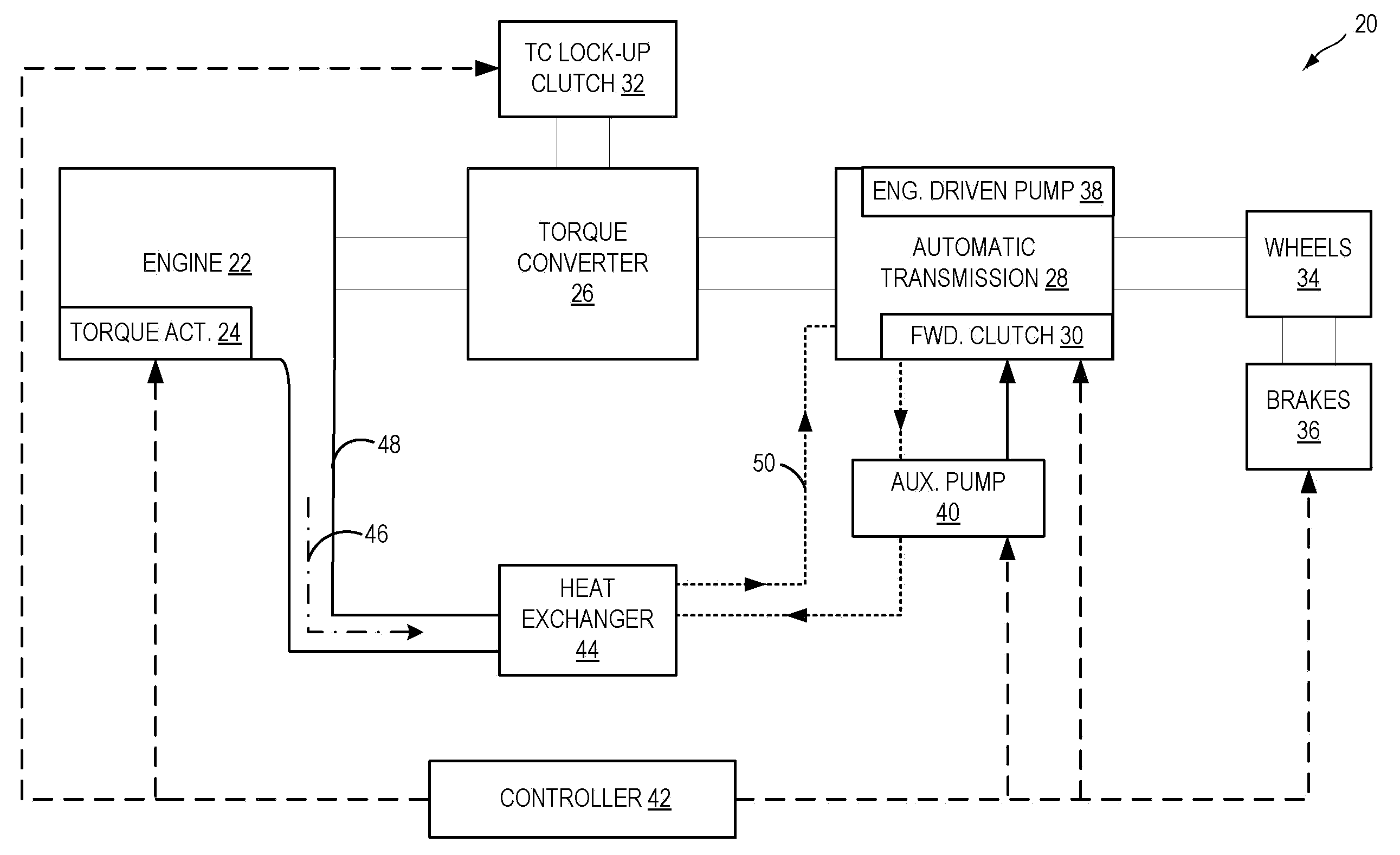
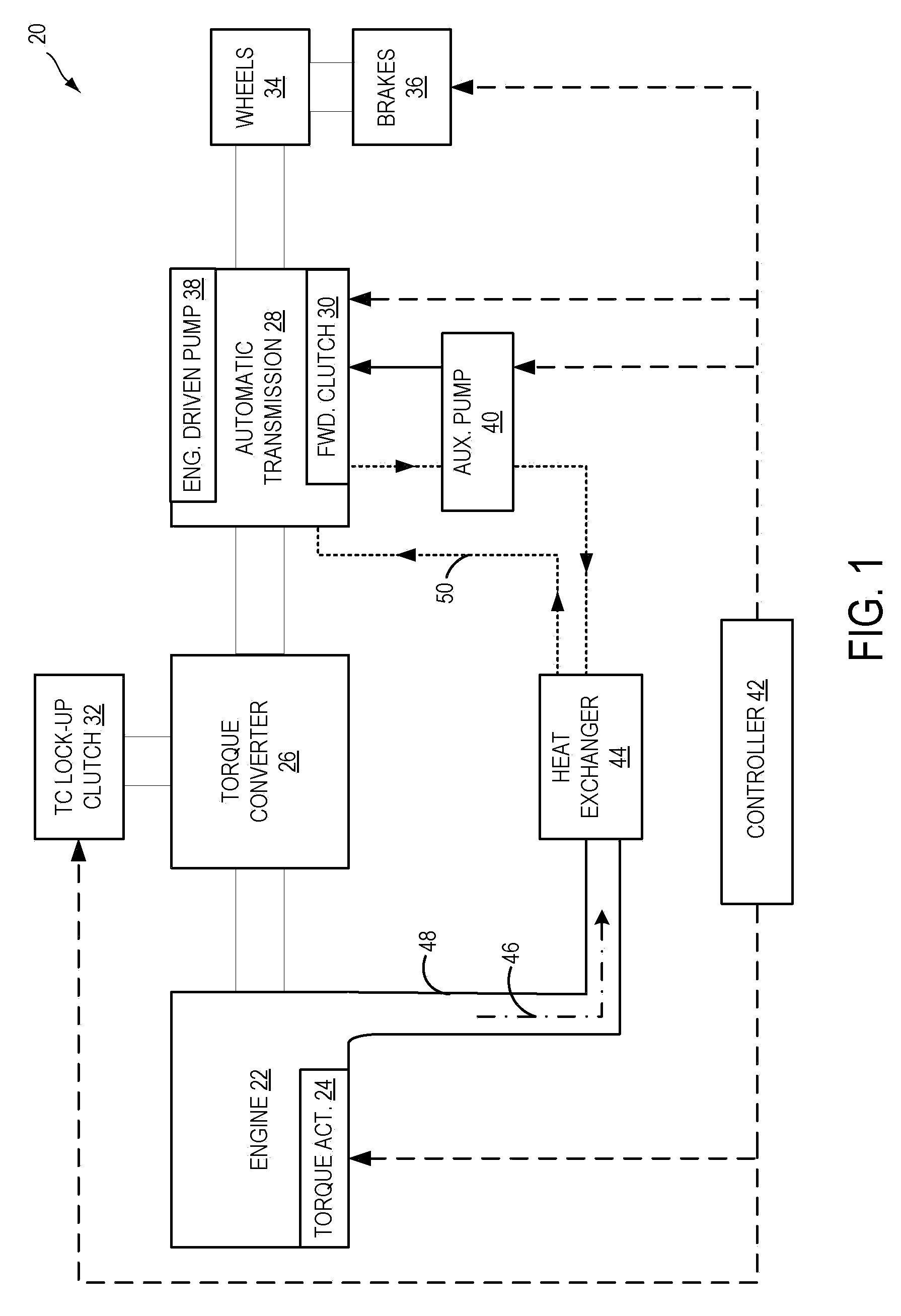
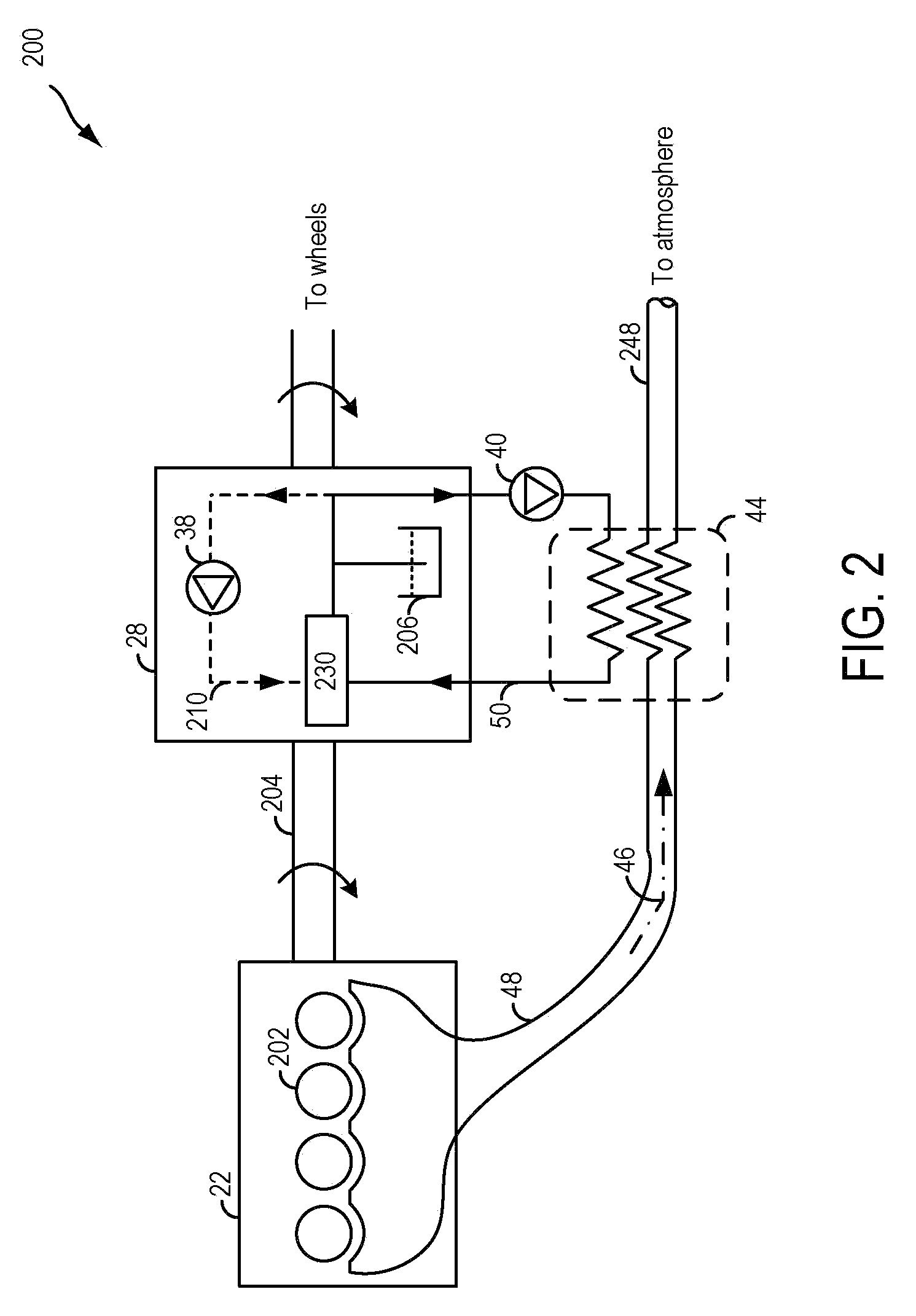
[0013]The following description relates to systems and methods for expediting heating of a transmission fluid, such as at engine cold start, to thereby improve engine restart quality and provide fuel economy. Transmission fluid may be heated by passage through a heat exchanger, configured, in one example, to draw heat from engine exhaust gas, as illustrated in FIG. 1. The heat exchanger may be coupled to an auxiliary fluid loop of a vehicle'auxiliary transmission fluid pump. As shown in FIG. 2, by operating the auxiliary transmission fluid pump, cold transmission fluid may be circulated through the heat exchanger of the auxiliary fluid loop to expedite fluid heating. As shown in FIG. 3, an engine control system may be configured to operate the auxiliary pump, in response to a transmission fluid temperature being below a threshold, to expedite transmission fluid heating while also operating the auxiliary pump during engine idle-stop conditions to generate pressure in the transmission...


PUM


Abstract

Systems and methods are provided for heating transmission fluid in a vehicle, the vehicle comprising an engine and a transmission, the engine including a heat exchanger. One example method comprises, during a first engine running condition, operating an auxiliary transmission fluid pump to generate pressure in the transmission fluid and pump transmission fluid to the heat exchanger, and during a second condition where the engine is not running, operating the auxiliary transmission fluid pump to generate pressure in the transmission fluid and pump transmission fluid to the heat exchanger.

Description

FIELD [0001]The present application relates to methods and systems for heating transmission fluid provided to an engine transmission.BACKGROUND AND SUMMARY [0002]Vehicles have been developed to perform an idle-stop when idle-stop conditions are met and automatically restart the engine when restart conditions are met. Such idle-stop systems enable fuel savings, reduction in exhaust emissions, reduction in noise, and the like. As such, a number of methods may be used to control the hydraulically operated transmission to improve idle-stops and subsequent restarts, when restart conditions are met.[0003]In one example approach, as illustrated by Nakamori et al. in U.S. Pat. No. 6,647,326, the hydraulic pressure and flow of transmission fluid (such as engine oil) to the various clutches and gears of the transmission may be maintained using a mechanical oil pump and an auxiliary electric oil pump. Specifically herein, hydraulic line pressure is maintained by the mechanical oil pump under e...

Claims


Application Information

Patent Timeline
Patent Type & Authority Applications(United States)
IPC IPC(8): F16H57/00
CPCF16H57/0413F16H57/0417Y10T477/653F16H61/0021F16H61/0031F16H57/0475
Inventor PURSIFULL, ROSS DYKSTRA
Owner FORD GLOBAL TECH LLC
Why Eureka
Try Eureka