
Apparatus for processing flat articles, in particular printed products

Inactive Publication Date: 2010-08-12
FERAG AG
View PDF5 Cites 3 Cited by
  • Summary
  • Abstract
  • Description
  • Claims
  • Application Information

AI Technical Summary

Benefits of technology

[0013]The apparatus comprises at least one rigid body, which can be rotated about an axis of rotation, e.g. a wheel or a carrying arm, and at least one tool, which is fastened on this body, can be moved along a circulatory path by virtue of the body being rotated and has a processing zone. This tool is, in particular, a welding tool with a welding bar as the processing zone. The tool is fastened on the body such that it can be rotated or pivoted about a pivot axis, wherein the pivoting position of the tool can be adjusted, in dependence on the rotary position of the rigid body, by means of a fixed-location control track (control cam) and a control element which interacts with the control track and is connected to the tool. According to the invention, the pivot axis is at a constant distance from the axis of rotation, and the processing zone of the tool is arranged in the immediate vicinity of the pivot axis, wherein the control element is spaced apart from the processing zone. This design has the advantage that the position of the processing zone in space is known precisely at any point in time because the processing zone is always located on a circular path of which the radius corresponds to the distance of the pivot axis from the center of rotation.
[0026]In particular, when a damping layer is present, the resilient mounting of the conveying support and / or of the supporting means serves, in particular, to compensate for disruption which results in the conveying support being deflected to an extent which is greater than that customary for normal processing.

Problems solved by technology

The forces which act on the tools here, however, may lead to wear.
This may give rise to problems when, for example, products of different thicknesses are processed.
Undesired torques arise here.
It is not possible, however, to control the orientation of the welding tools in the case of the apparatus according to WO-A 2005 / 118402.
A hitherto unsolved problem in respect of a counterpart tool which is fixed in location overall, e.g. a conveying belt, is constituted by relatively large degrees of deflection of the conveying belt caused directly or indirectly by the tools, e.g. when the latter, on account of inaccurate supply, strike against a product rather than coming between the products.
In the case of a stiff conveying belt, this may result in the tools jamming or being damaged.
An elastic conveying belt can compensate for this in some cases, but does not appear, in normal circumstances, to meet the requirements relating to precise feeding of the products (no sagging).

Method used


Image

  • Apparatus for processing flat articles, in particular printed products
  • Apparatus for processing flat articles, in particular printed products
  • Apparatus for processing flat articles, in particular printed products

Examples


Embodiment Construction

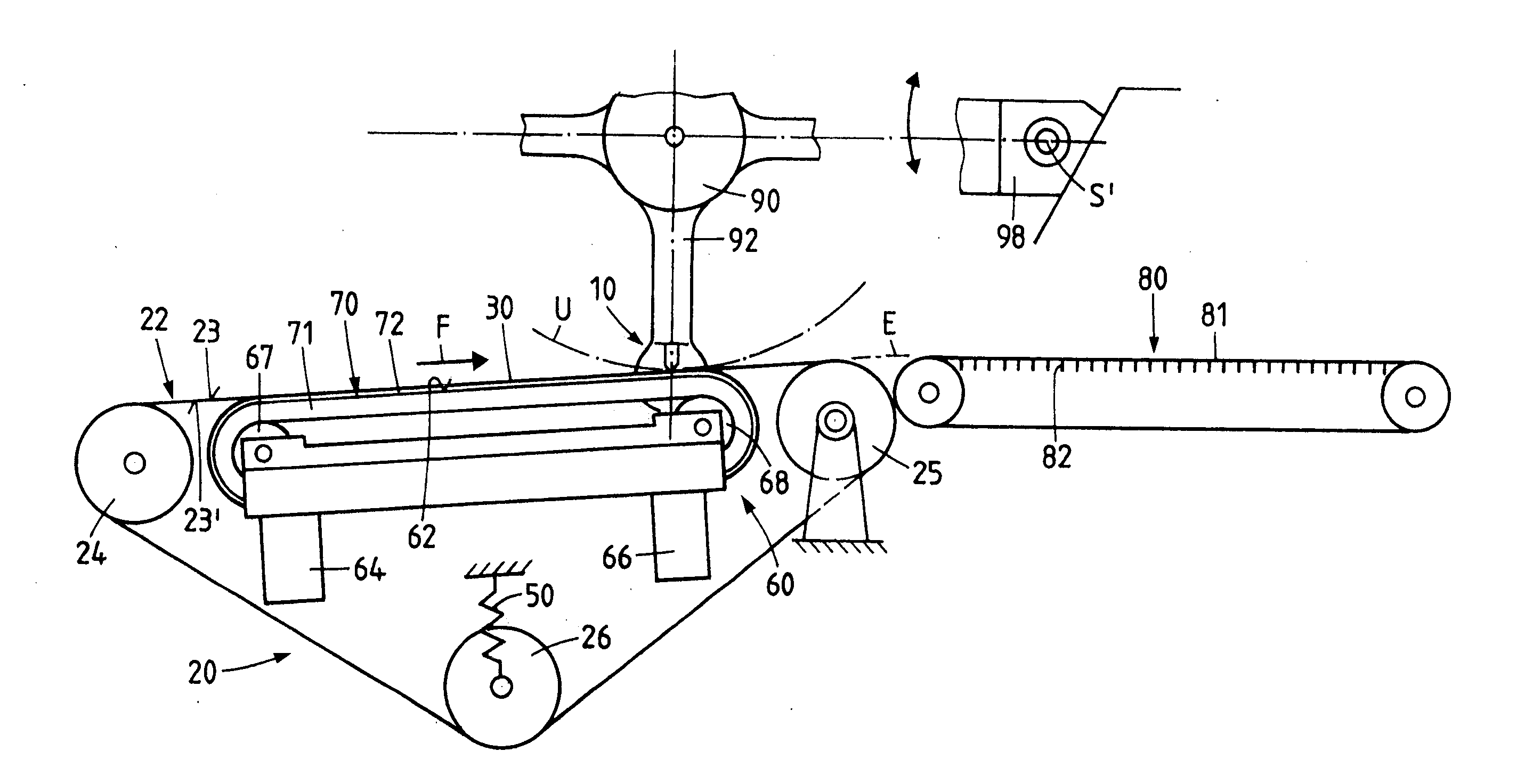
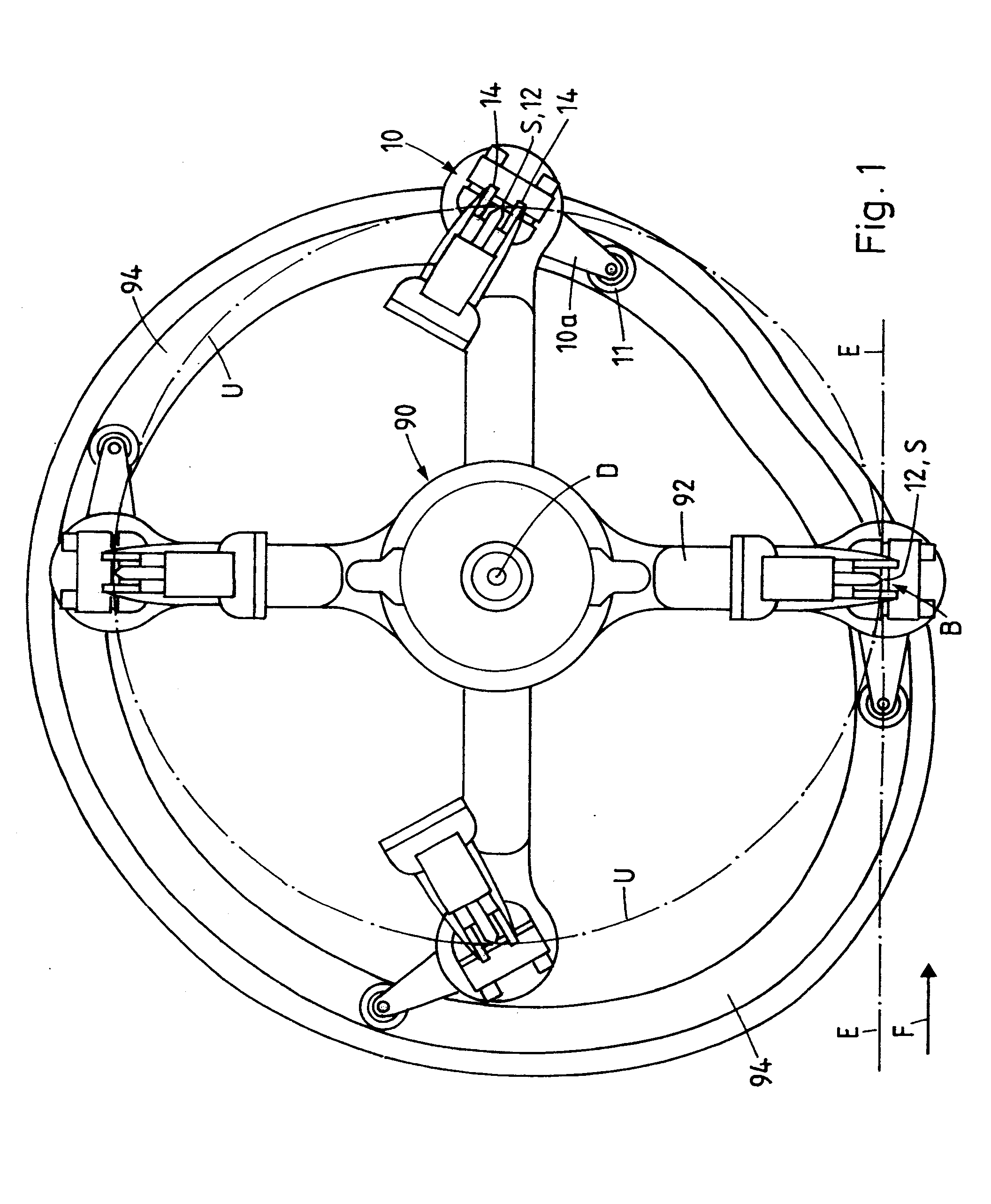
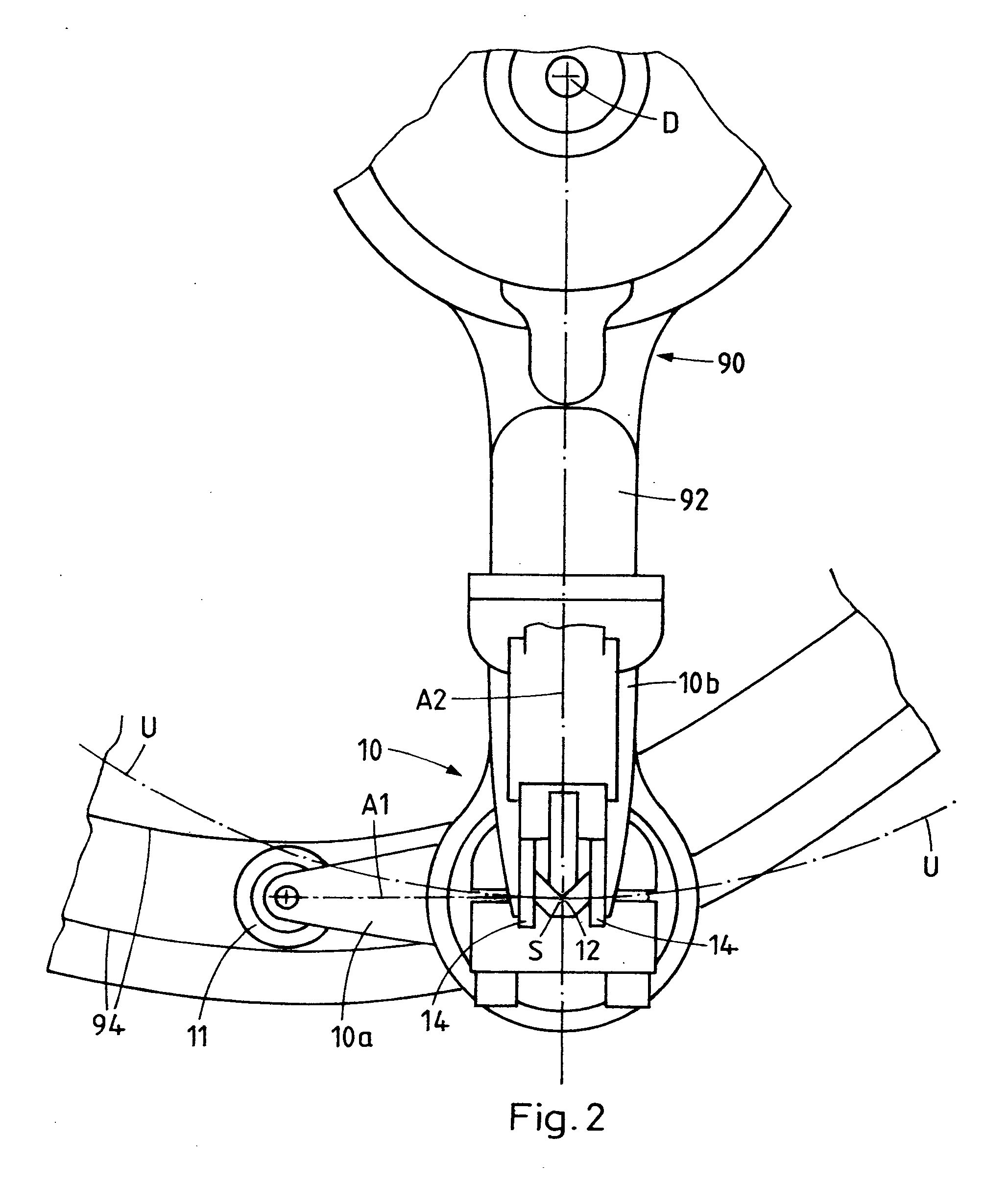
[0037]FIG. 1 shows a view of a processing apparatus according to the invention with a rigid body 90 which can be rotated about an axis of rotation D. The body 90 has four carrying arms 92, and a tool 10 is fitted at the distal ends of each of these carrying arms, at a constant distance from the axis of rotation D, such that it can be pivoted about a pivot axis S. The angle between the carrying arms 92 may be constant. It is preferred that the carrying arms can be moved in a controlled manner relative to one another individually or in pairs (e.g. mutually opposite carrying arms 92), in which case it is possible to vary the speed of the carrying arms 92 along the circulatory path U. The tools 10 serve for processing products or a material web conveyed past the processing apparatus in a conveying plane E, along a conveying direction F.

[0038]The tools 10 are illustrated in detail in FIG. 2. These tools are welding tools with a processing zone 12 in the form of a welding bar and two resi...


PUM

PropertyMeasurementUnit
Angleaaaaaaaaaa
Temperatureaaaaaaaaaa
Lengthaaaaaaaaaa

Abstract

A device for processing flat objects (40) delivered successively in a delivery direction, in particular print shop products, and / to a continuously advanced material web (42). The device, which is to be used particularly for welding a material web, includes at least one rigid body (90) that can be pivoted about an axis of rotation (D) and at least one tool (10) having a processing-effective zone (12), the tool being attached to the body (90) and movable along an orbit (U) by rotating the body (90). The tool is attached to the body (90) pivotally or rotatably about a pivot axis (S). The pivot position of the tool can be adjusted as a function of the rotational position of the rigid body by means of a stationary control gate and a control element interacting with the control gate and connected to the tool.

Description

BACKGROUND OF THE INVENTION[0001]1. Field of the Invention[0002]The invention concerns the field of conveying and packaging technology and relates to an apparatus for processing continuously conveyed flat products, in particular printed products, and / or a continuously moving, quasi endless material web, in particular a sheet-material web.[0003]2. Description of Related Art[0004]Processing products in a conveying stream requires, on the one hand, high processing speeds and a straightforward, low-wear design for the mechanical components which means that the latter are not particularly susceptible to malfunctioning and, on the other hand, precise control of the movement of the tools and of the products and a processing time which is as long as possible. Most processes used for processing products or a material web, e.g. welding, cutting or printing, also require a certain counterpressure or resistance to be applied by a counterpart tool which interacts with the actual tool. Some of th...

Claims


Application Information

Patent Timeline
IPC IPC(8): B65B11/00
CPCB65B9/067Y10T156/1737B65B51/16B65B51/306B29C66/83511B65B51/30B29C65/7841B29C66/1122B29C66/344B29C66/4312B29C66/81417B29C66/8161B29C66/82263B29C66/83421B29C66/849B29C65/02Y10T156/1712B65B25/14B29C66/81241B29C66/81821B29C66/00441B29C66/8122B29K2827/18
Inventor DAX, ROMANLUGINBUHL, THOMAS
Owner FERAG AG
Features
  • Generate Ideas
  • Intellectual Property
  • Life Sciences
  • Materials
  • Tech Scout
  • Unparalleled Data Quality
  • Higher Quality Content
  • 60% Fewer Hallucinations
Learn More