Refrigerant system with intercooler and liquid/vapor injection

Active Publication Date: 2010-08-12
CARRIER CORP
View PDF5 Cites 53 Cited by
  • Summary
  • Abstract
  • Description
  • Claims
  • Application Information

AI Technical Summary

Benefits of technology

[0011]The intercooler increases system capacity and improves efficiency, since the compressor discharge temperature is reduced, and the heat rejecting heat exchanger is typically capable to cool refrigerant to a lower temperature, providing a higher cooling potential in the evaporator. Additionally, a steeper slope of the isentropic lines for the downstream compression stages allows for a higher compressor isentropic efficiency. Furthermore, lower discharge temperatu

Problems solved by technology

If the compression ratio for the compressor system is high (which is typically the case for two-stage compression systems) and/or refrigerant suction temperature is high (which is often the case for a refrigerant system equipped with a liquid-suction heat exchanger), then refrigerant discharge temperature can also become extremely high, and in many cases may exceed the limit defined

Method used


Image

  • Refrigerant system with intercooler and liquid/vapor injection
  • Refrigerant system with intercooler and liquid/vapor injection

Examples


Example

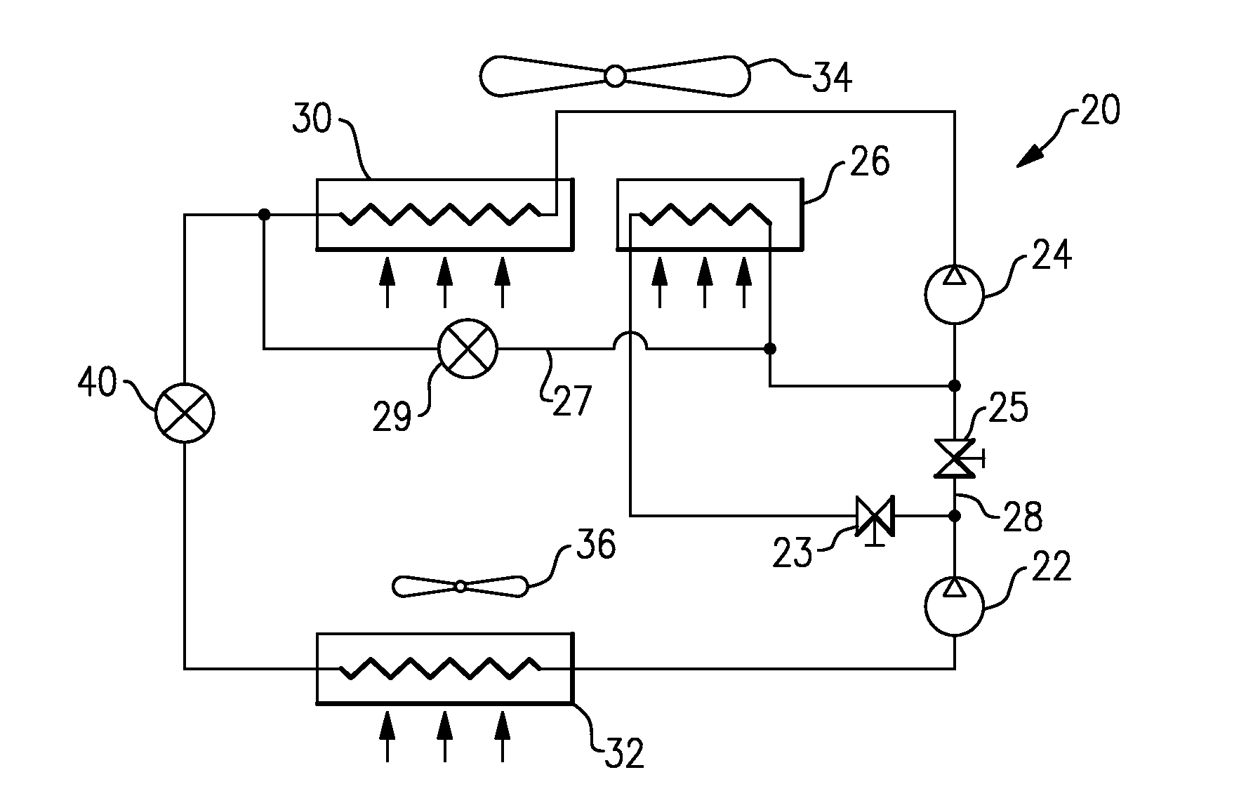
[0017]A refrigerant system 20 is illustrated in FIG. 1 having a lower stage compressor 22 and a higher stage compressor 24. While only two sequential stages are shown, additional stages may also be incorporated in series in this invention. Also, instead of separate compressors connected in sequence, a multi-stage single compressor arrangement can be employed and equally benefit from the present invention. For instance, the two illustrated, separate compression members may be represented by different banks of cylinders connected in series for a reciprocating compressor. As known, refrigerant compressed by a lower stage compressor 22 to an intermediate pressure is delivered from a discharge outlet of this lower stage compressor 22 to the suction inlet of the higher stage compressor 24. An intercooler 26 is positioned between the two stages to accept refrigerant from a discharge outlet of the lower stage compressor 22. This refrigerant is cooled by a secondary media, such as ambient ai...


PUM


Abstract

A refrigerant system is provided with at least two sequential stages of compression. An intercooler is positioned intermediate the two stages. The refrigerant flowing through the intercooler is cooled by a secondary fluid such as ambient air. A vapor/liquid injection function is also provided for the refrigerant system. The intercooler function and the vapor/liquid injection function are selectively activated on demand depending on environmental conditions and thermal load in a conditioned space. This invention is particularly important for the CO2 refrigerant systems operating in the transcritical cycle.

Description

BACKGROUND OF THE INVENTION[0001]This application relates to refrigerant systems, wherein the compressor is a multi-stage compressor (e.g. a two-stage compressor), and wherein an intercooler and liquid / vapor injection are provided between the compression stages. The intercooler is preferably subjected to an ambient airflow and, such that the cooling in the intercooler is preferably provided by circuitry and components that are already part of the refrigerant system.[0002]Air conditioning, heat pump and refrigeration systems provide cooling or heating of a secondary fluid, such as air, delivered into a climate-controlled environment. A typical basic air conditioning, heat pump or refrigeration system includes a compressor, an expansion device, a heat rejecting heat exchanger and a heat accepting heat exchanger. The heat rejecting heat exchanger is either a condenser for subcritical applications or a gas cooler for transcritical applications, while a heat accepting heat exchanger is t...

Claims


Application Information

Patent Timeline
IPC IPC(8): F25B1/00F25B1/10F25B41/00
CPCF25B1/10F25B49/027F25B2400/04F25B2400/072F25B2400/13F25B2309/06
Inventor TARAS, MICHAEL F.LIFSON, ALEXANDER
Owner CARRIER CORP
Why Eureka
Try Eureka