
Wireless communication system and wireless communication control method

Active Publication Date: 2020-02-13
NIPPON TELEGRAPH & TELEPHONE CORP
View PDF0 Cites 2 Cited by
  • Summary
  • Abstract
  • Description
  • Claims
  • Application Information

AI Technical Summary

Benefits of technology

The present invention is related to a method for controlling network access points (APs) and user equipments (UEs) in a network using a congestion level to optimize transmission and reduce interference. The technical effects of this invention are as follows: 1. Solving exposed situations: in transmission or reception, APs and UEs can be connected to different networks or connected APs. The invention allows for the resolution of exposed situations, which helps maintain the necessary quality of the APs and UEs, and increases the system capacity of the network. 2. Improved judgment precision: based on the congestion levels in transmission and reception, the invention sets thresholds and aggregation periods to determine the likelihood of congestion situations. This helps avoid unintended changes in network or connected APs, reducing interference and improving network efficiency. 3. Controlling network without extending standard specification: the invention can be easily integrated into the existing standards without consuming radio resources. This makes it easy to control network access and reduces the impact on the network. In summary, the invention improves network efficiency, reduces interference, and optimizes network access through congestion level control.

Problems solved by technology

In a control method that uses RTS / CTS, at a point in time when the reception station receives an RTS frame, when a signal is receiving from any other wireless station, or a NAV is set, responding with the CTS frame destined for the transmission station is not possible.
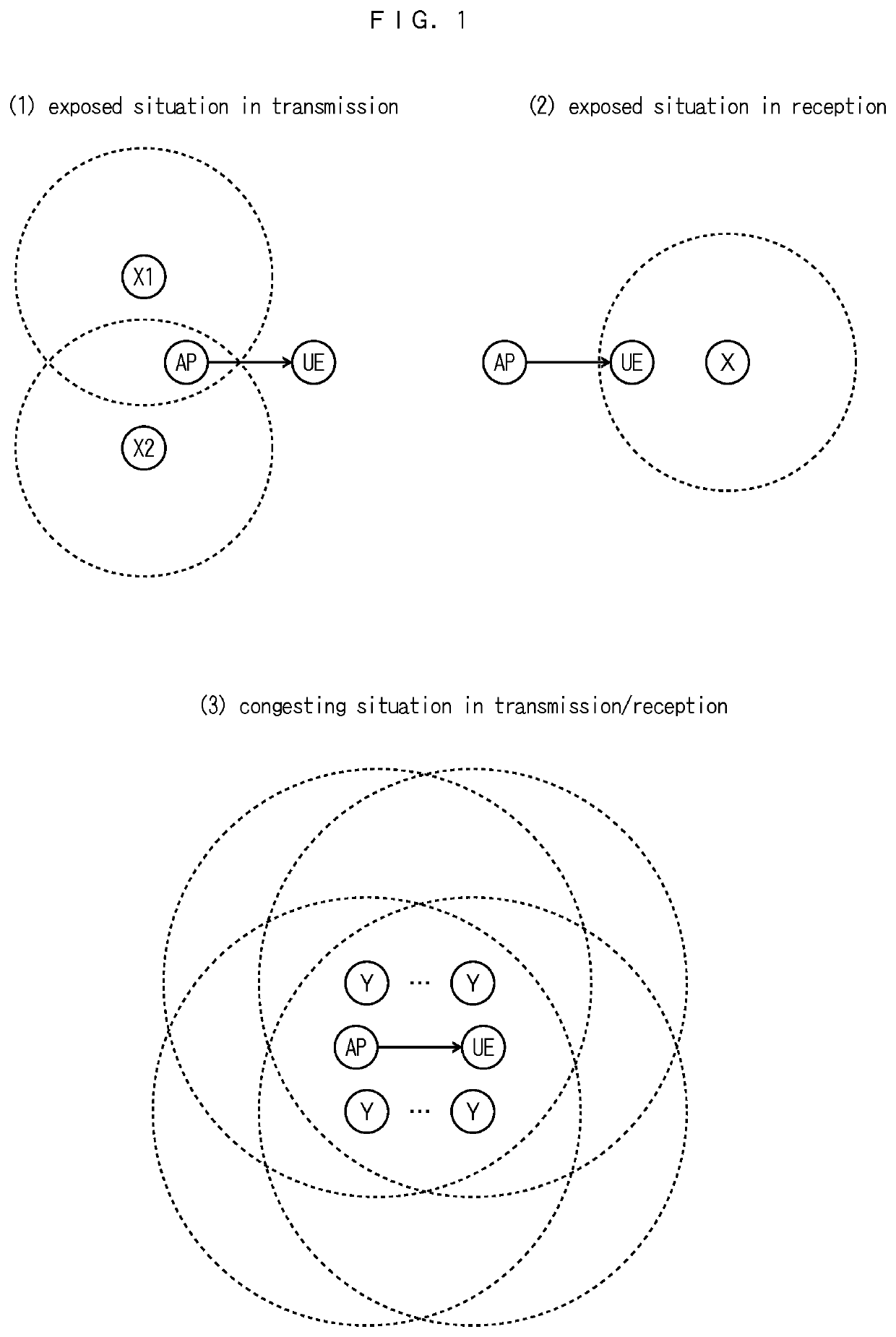
Furthermore, the exposed-station problem occurs easily as well in the dense environment of the AP.
In a situation where the radio wave strength, the signal-to-noise ratio, or the data rate is high, the hidden-station problem and the exposed-station problem can occur as well.
Furthermore, when a radio wave environment in the AP changes, such as a new stationary AP or a mobile AP such as a mobile router appears, or when an influence such as a limitation on an available channel, which results from Dynamic Frequency Selection (DFS), is exerted, this change cannot be dealt with, only using the manual channel setting or the channel automatic setting at the time of activation of the AP.
Furthermore, because the hidden-station problem and the exposed-station problem are possibly caused by the presence of the hidden stations that are stations which cannot mutually detect a signal, the hidden-station relation cannot be recognized with the number of SSIDs that are detected in the AP.
Therefore, although the function of periodically performing the automatic setting of the channel is provided, because the hidden-station problem and the exposed-station problem cannot be recognized, the automatic setting does not function effectively.

Method used


Image

  • Wireless communication system and wireless communication control method
  • Wireless communication system and wireless communication control method
  • Wireless communication system and wireless communication control method

Examples


example 1

of a Control Procedure for the UE, which is Based on the Required Quality of the UE

[0075]FIG. 6 illustrates Example 1 of a control procedure for the UE, which is based on the required quality of the UE. Note that it is assumed that the UE is already connected to the AP.

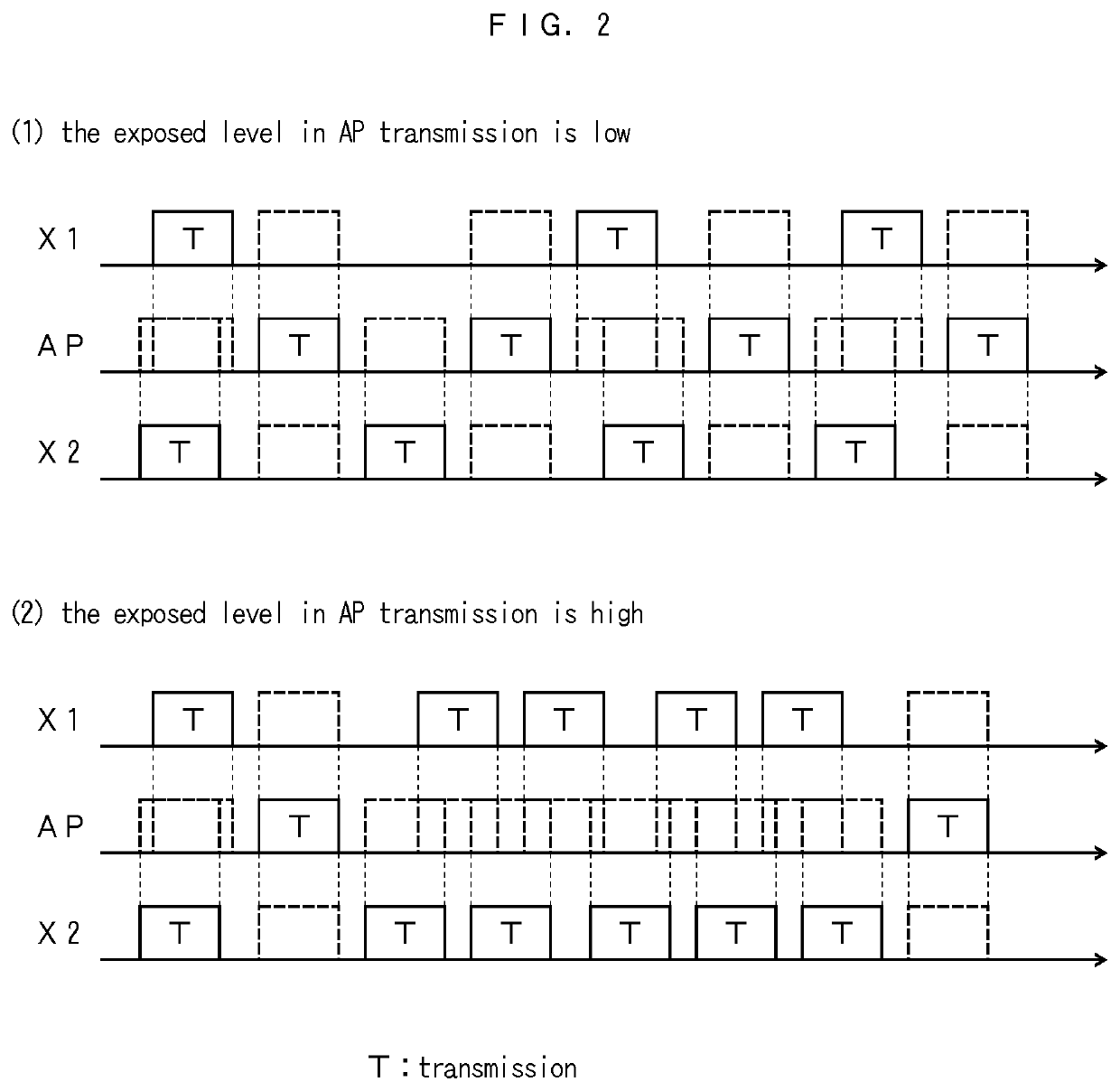
[0076]In FIG. 6, the UE calculates the beacon signal transmission delay α from the reception history of the beacon signal that is transmitted from the connected AP (S1). The beacon signal that is scheduled for transmission at the TBTT, although delayed according to a CSMA / CA procedure in the AP, is normally transmitted by the next TBTT Therefore, the TBTT is recognized in the UE, and thus the beacon signal transmission delay α can be calculated from the Time Stamp that is included in the received beacon signal. At this point, the beacon signal transmission failure f(α) in the AP keeps estimated from the history of the beacon signal transmission delay α (S2).

[0077]Next, the beacon signal transmission delay α is aggrega...

example 2

of the Control Procedure for Determining the Connected AP of the UE, which is Based on the Required Quality of the UE

[0087]FIG. 7 illustrates Example 2 of the control procedure for determining the connected AP of the UE, which is based on the required quality of the UE. At this point, when the UE is not connected to the AP, when a roaming procedure for make a connection to a new AP is started, when instruction to change the network or the connected AP is received in Example 1 of the control procedure, or in other cases, a procedure for searching for a new AP that satisfies the required quality is described.

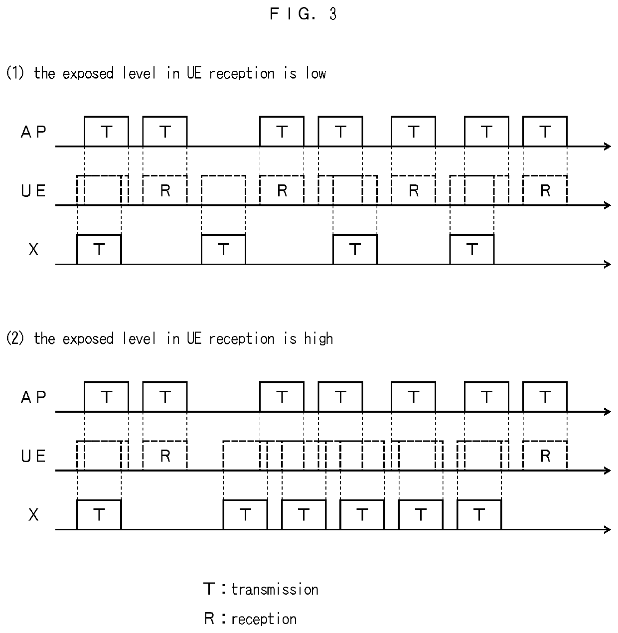
[0088]In the same manner as in Example 1 of the control procedure, the judgment threshold S is set against which it is judged whether or not the exposed level in transmission that is based on the beacon signal transmission delay α can satisfy the required quality, and the judgment threshold R is set against which it is judged whether or not the exposed level in reception that is b...

example 3

of the Control Procedure for the AP, which is Based on the Expected Quality of the AP

[0098]The AP can change a channel that is to be used for communication. Therefore, when the AP itself is in the exposed situation in transmission, in some cases, the exposed situation in transmission can be avoided by changing a channel. However, although the exposed situation in transmission is entered, when the exposed level in transmission is low and the expected quality of the AP is ensured, there is no need to perform channel control. It is noted that as the expected qualities of the AP, in the same manner as in Example 1 of the control procedure, throughput, latency, jitter, packet loss, and the like are given.

[0099]FIG. 8 illustrates Example 3 of the control procedure for the AP, which is based on the expected quality of the AP.

[0100]In FIG. 8, the AP calculates the beacon signal transmission delay α from the transmission history of the transmitted beacon signal (S31). It is noted that the AP...


PUM


Abstract

An AP and UE, which perform access control using CSMA / CA, perform a step judging an exposed level in transmission of the AP based on a congesting level in transmission, which is caused by a wireless station in defer transmission that is in a neighborhood of the AP; a step judging an exposed level in reception of the UE based on a congesting level in reception, which is caused by a wireless station in defer transmission that is in a neighborhood of the UE; and a step performing control which changes a channel of the AP, when the exposed level in transmission cannot satisfy expected quality of the AP, and performing control which changes a connected AP of the UE, or control which changes to other network, when the exposed level in transmission or in reception cannot satisfy required quality of the UE or the expected quality of the AP.

Description

CROSS-REFERENCE TO RELATED APPLICATION[0001]This application is a U.S. National Phase Application claiming the benefit of prior filed International Application Number PCT / JP2018 / 012803, filed on Mar. 28, 2018, in which the International Application claims priority from Japanese Patent Application Number 2017-067259, filed on Mar. 30, 2017, the entire contents of which are incorporated herein by reference.TECHNICAL FIELD[0002]The present invention relates to a wireless communication system in which multiple wireless stations share the same wireless channel, and perform wireless communication using Carrier Sense Multiple Access / Collision Avoidance (CSMA / CA). Particularly, the present invention relates to a wireless communication system and a wireless communication control method, in each of which an exposed situation in transmission in which a transmission opportunity acquisition rate for a transmission station, which is caused by a wireless station that has a hidden-station relation,...

Claims


Application Information

Patent Timeline
IPC IPC(8): H04W74/08
CPCH04W74/085H04W84/12H04W48/20H04W74/0808H04W48/16H04W48/18H04W74/0816
Inventor INOKI, AKIYOSHIABEYSEKERA, HIRANTHAMATSUI, MUNEHIROKAWAMURA, KENICHITAKATORI, YASUSHIICHIKAWA, TAKEOKISHIDA, AKIRAMORIHIRO, YOSHIFUMIASAI, TAKAHIRO
Owner NIPPON TELEGRAPH & TELEPHONE CORP
Learn More