Rotary index device in machine tool

a technology of rotary index and machine tool, which is applied in the direction of manufacturing tools, mechanical equipment, precision positioning equipment, etc., can solve the problems of etc., and achieve strong clamping force, prevent deformation of machining accuracy, and stable clamping

Inactive Publication Date: 2010-08-12
TSUDAKOMA KOGYO KK
View PDF22 Cites 11 Cited by
  • Summary
  • Abstract
  • Description
  • Claims
  • Application Information

AI Technical Summary

Benefits of technology

[0018]With the rotary index device (1) according to claim 1, the clamp disk extending in the radial direction of the rotating shaft is not clamped at the outer peripheral end portion of the clamp disk unlike the disk-type clamp device of the related art, or the pressure of the working fluid does not directly act on the housing in the radial direction of the rotating shaft unlike the sleeve-type clamp device of the related art. Thus, with the invention according to claim 1, since the indexed angular position is not deviated or the rotating shaft (4) is not inclined, the machining accuracy can be prevented from being degraded. In particular, since the pressing force conversion means (9) receives the pressing force from the tapered surface (8) when the piston member (7) is displaced, and the pressing force conversion means (9) causes the pressing force to act as a clamp force in the radial direction of the rotating shaft (4), the clamp force necessary for clamping can be provided. The rotating shaft (4) can be correctly clamped without the indexed angular position deviated.
[0019]According to claim 2, since the plurality of pressing members (11) are provided between the piston member (7) and the rotational body (5) and arranged in the circumferential direction of the rotating shaft (4), the clamp force can act uniformly on the circumference of the rotating shaft (4).
[0020]According to claim 3, the pressing members (11) are the lever members (12), and each lever member (12) is formed such that the distance from the effort portion (13) to the fulcrum portion (15) is larger than the distance from the fulcrum portion (15) to the load portion (14). The pressing force acting on the lever (12) from the piston member (7) is increased and then acts on the rotational body (5). Thus, a strong clamp force can be provided.
[0021]According to claim 4, the clamp member (16) fixed to the housing (2) non-rotatably relative to the housing (2) is provided, and the ring-shaped, deformable, thin-wall cylindrical portion (17), which is integrated with the clamp member (16), is arranged between the pressing force conversion means (9) and the rotational body (5). Thus, the clamp force can act substantially uniformly on a surface to be pressed of the rotational body (5). Also, the thin-wall cylindrical portion (17) frictionally contacts the surface to be pressed of the rotational body (5). Thus, a force in a rotational direction does not act on the pressing force conversion means (9) from the rotating shaft (4), and clamping becomes stable.
[0022]According to claim 5, since the angle of the tapered surface (8) of the piston member (7) to the rotational axis is smaller than 45 degrees, the pressing force acting on the lever member (12) from the piston member (7) is increased. Thus, a further strong clamp force can be provided. In particular, since the pressing force conversion means (9) is formed by combining two such force-increasing mechanisms, a strong clamp force that can be used for machining with a high load can be provided.

Problems solved by technology

Consequently, the indexed angular position of the rotating shaft may be deviated, and machining accuracy may be degraded.
Consequently, the machining accuracy may be degraded.

Method used


Image

  • Rotary index device in machine tool
  • Rotary index device in machine tool
  • Rotary index device in machine tool

Examples


Embodiment Construction

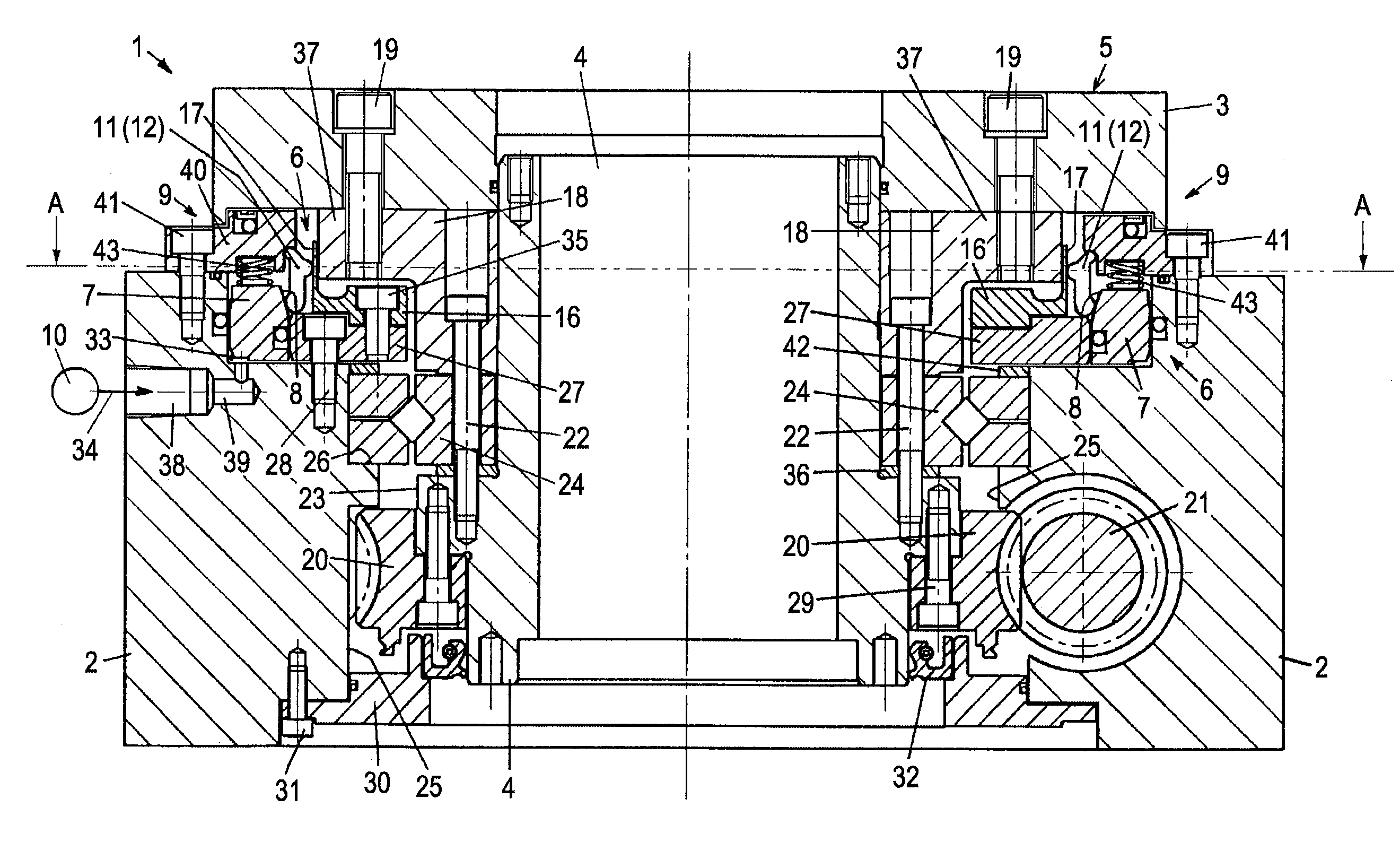
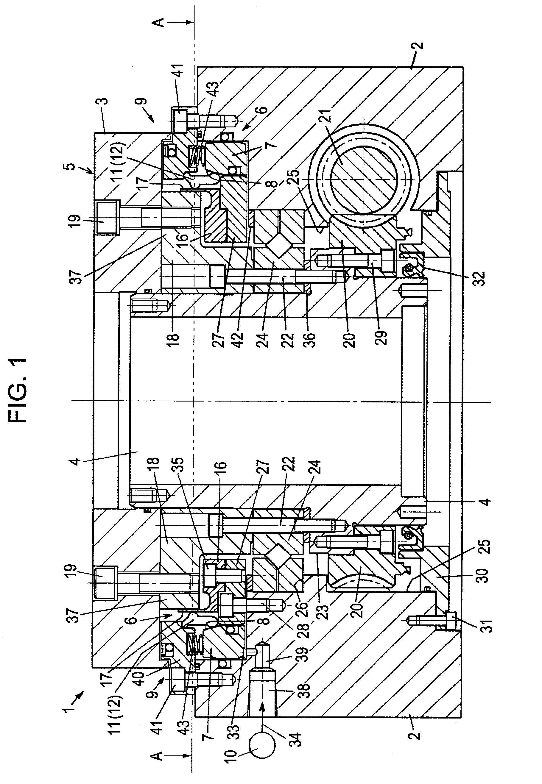
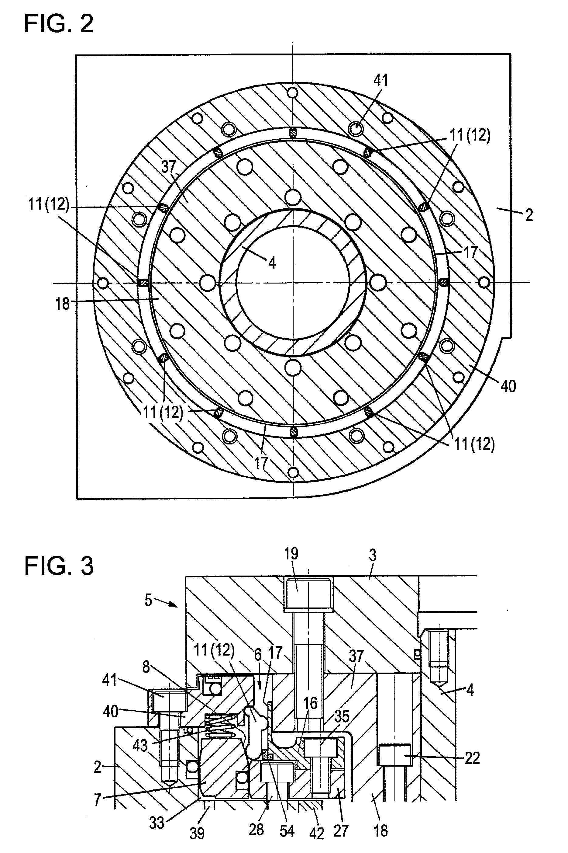
[0086]FIGS. 1 to 4 illustrate a representative embodiment in which a rotary index device 1 in a machine tool according to the present invention is applied to a rotary table device. Referring to FIGS. 1 to 4, the rotary index device 1 in a machine tool includes a rotating shaft 4 provided rotatably in a housing 2, a rotational body 5 including the rotating shaft 4, and a clamp device 6 for causing a pressing force to act on the rotational body 5 in a radial direction of the rotating shaft 4 and holding a rotational angular position of the rotational body 5 after indexing.

[0087]The rotating shaft 4 is, for example, hollow. The rotating shaft 4 is provided rotatably within a housing hole 25 of the housing 2. A rotary table 3 is relatively non-rotatably attached to an end portion of the rotating shaft 4. The rotary table 3 serves as a rotation object member. The rotary table 3 is arranged in parallel to a surface of the block-shaped housing 2. The rotary table 3 is fitted to the rotatin...


PUM


Abstract

A rotary index device in a machine tool includes a rotating shaft; and a clamp device. The clamp device includes a piston member provided displaceably in a direction along a rotational axis of the rotating shaft and having a tapered surface formed on a side surface thereof on a clamp position side, pressing force conversion means, for receiving a pressing force from the piston member when the piston member is displaced, converting the pressing force into a force in the radial direction of the rotating shaft, and causing the converted force to act on the rotational body, and urging means for urging the piston member in a direction in which the pressing force conversion means generates the pressing force in the radial direction of the rotating shaft.

Description

TECHNICAL FIELD[0001]The present invention relates to a device in a machine tool, the device which rotates a rotary table and indexes to bring a workpiece on the rotary table to a predetermined rotational angle.BACKGROUND ART[0002]Patent document 1 discloses a disk-type clamp device, and patent document 2 discloses a sleeve-type clamp device.[0003]The disk-type clamp device typically has a clamp disk fixed to a rotating shaft and extending in a radial direction of the rotating shaft. An outer peripheral end portion of the clamp disk is clamped by a clamp surface of a housing and a piston member or the like after indexing of the rotating shaft. Thus, the indexed angular position of the rotating shaft is held.[0004]Since the disk-type clamp device holds the angular position by clamping the outer peripheral end portion of the thin-plate clamp disk, a load in a rotational direction is applied to the rotating shaft during machining of a workpiece. Thus, deflection may occur between the f...

Claims


Application Information

Patent Timeline
Patent Type & Authority Applications(United States)
IPC IPC(8): B23Q16/10B23Q1/26
CPCB23Q16/102Y10T74/1494B23Q16/107
Inventor TATSUDA, YOSHINORI
Owner TSUDAKOMA KOGYO KK
Why Eureka
Try Eureka