Conveyor system

a conveyor system and belt conveyor technology, applied in conveyors, conveyor parts, rollerways, etc., can solve the problems of inability to move the workpiece carrier, inability to check the setting, and high cost of the friction clutch

Inactive Publication Date: 2010-08-12
CERATIS
View PDF8 Cites 20 Cited by
  • Summary
  • Abstract
  • Description
  • Claims
  • Application Information

AI Technical Summary

Benefits of technology

[0011]It is an object of the invention to provide a conveyor system, especially a roller conveyor, allowing to realize curves and branches in a simple manner. In addition, it is preferably provided to allow for a simple back-up situation.

Problems solved by technology

Such friction clutches are expensive and maintenance-intensive.
Because of wear, the setting has to be checked in regular intervals.
At curves or branches, however, it is not possible to move the workpiece carrier by means of such disc-shaped transmission elements that engage in slot-shaped recesses in the bottom face of the workpiece carrier, since, at a curve or a branch, the workpiece carrier must be moved transversely to its conveying direction.
Such a lateral displacement of the workpiece carrier on the rollers, necessary at branches or bends, is not possible when disc-shaped transmission elements are provided that engage in slot-shaped recesses in the bottom face of the workpiece carrier.

Method used


Image

  • Conveyor system
  • Conveyor system
  • Conveyor system

Examples


Embodiment Construction

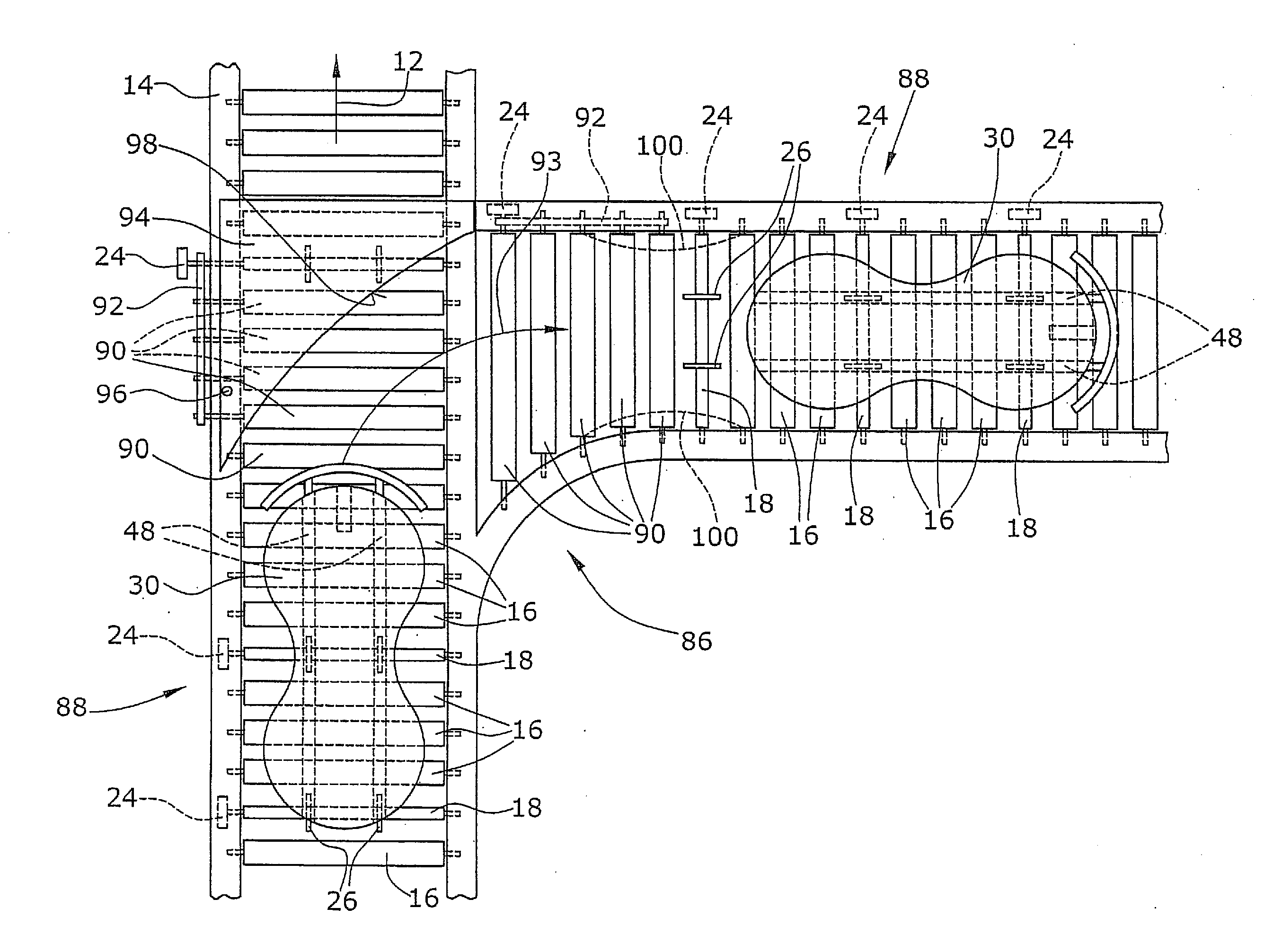
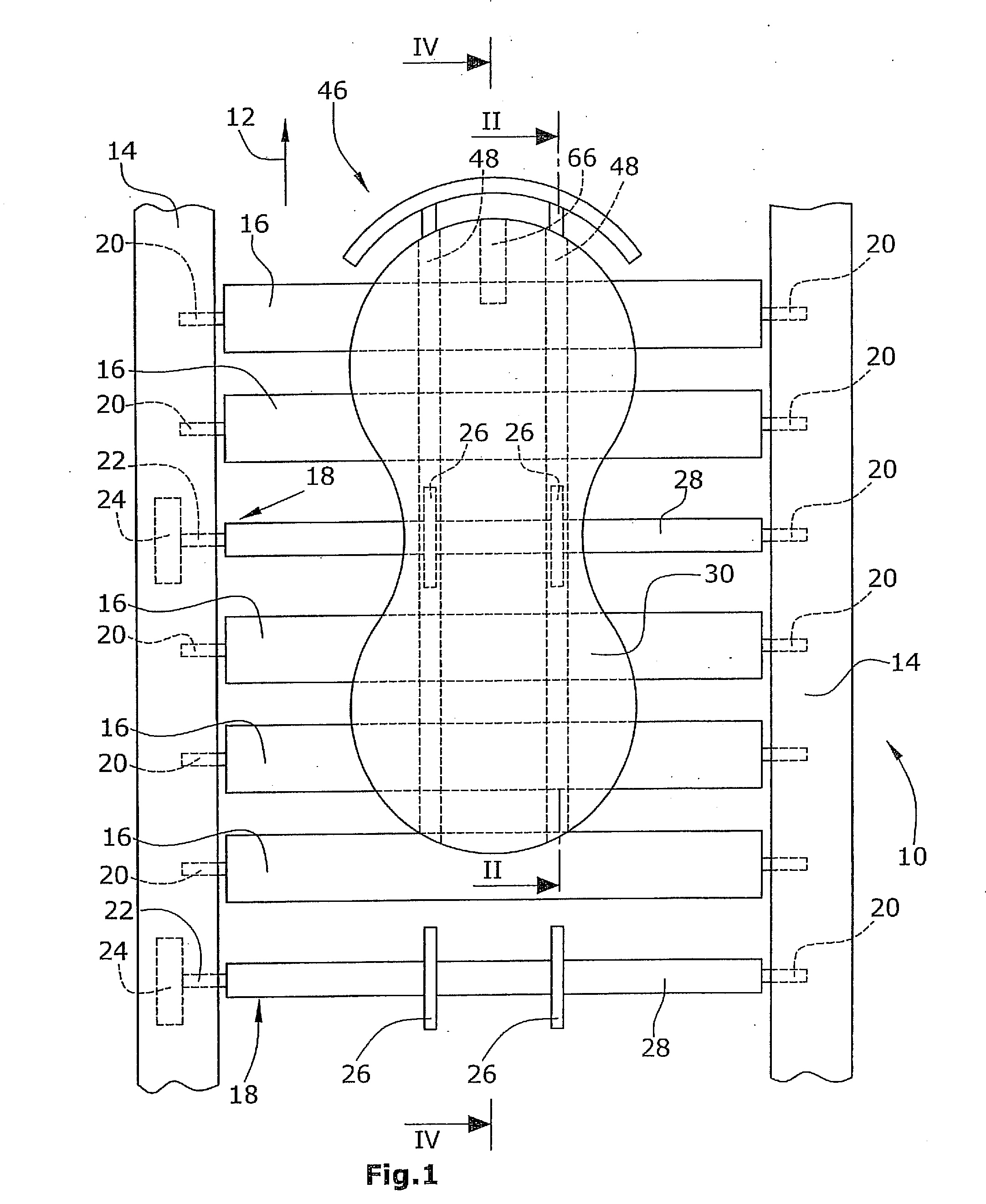
[0038]The friction conveyor system comprises a conveyor means 10. The conveyor means 10 has frames 14 extending in the longitudinal or conveying direction 12. In addition, the conveyor system may comprise switches and curves not illustrated in the Figures. In the embodiment illustrated, the frames 14 support freely rotatable supporting rollers 16 and conveyor rollers 18. The supporting rollers are supported in a freely rotatable manner in the frames 14 through axes 20 and corresponding bearings. In the embodiment illustrated, the driven conveyor elements (conveyor rollers 18) also extend over the entire width of the conveyor means 10 such that one side of the driven conveyor rollers 18 is supported for free rotation in the frame 14 via a shaft 20. The second shaft 22 of the driven conveyor means 18 is driven by and connected with an electric motor 24.

[0039]In the embodiment illustrated, the conveyor rollers 16 that are not driven and the driven conveyor elements 18 extend over the e...


PUM


Abstract

A conveyor system, which in particular is a roller conveyor, has freely rotatable supporting rollers (16) as well as transmission elements (26) driven by shafts (18). The transmission elements (26) are disc-shaped and engage into slot-shaped recesses (48) formed in the bottom face (34) of a workpiece carrier (30). In a curve and/or branch (86), no disc-shaped transmission elements (26) are provided. The workpiece carrier (30) is moved in a curve and/or branch (86) by driven conveyor rollers (90) provided there. The conveyor rollers (90) transmit force to the bottom face (34) of the workpiece carrier (30) by friction.

Description

BACKGROUND OF THE INVENTION[0001]1. Field of the Invention[0002]The invention refers to a conveyor system, in particular a friction conveyor system, comprising a conveyor means such as a roller conveyor, a belt conveyor or a plate conveyor, on which conveyor means workpiece carriers are loosely placed. In particular, the invention refers to a roller conveyor in which the workpiece carriers are displaced by means of friction.[0003]2. Description of Related Art[0004]Especially in mass production, conveyor means are used to transport workpieces between individual workplaces where the workpieces are assembled or worked upon, for instance. For this purpose, the workpieces are arranged on workpiece carriers which are moved together with the workpieces by corresponding conveyor means. When workpiece carriers are to be moved, friction conveyors are known to be suitable means. With friction conveyors, the workpieces are not fixedly connected with conveyor means but rest on rollers, for insta...

Claims


Application Information

Patent Timeline
Patent Type & Authority Applications(United States)
IPC IPC(8): B65G13/071
CPCB65G13/10B65G47/261B65G17/002
Inventor KRUPS, PETERKRUPS, MATTHIAS
Owner CERATIS
Why Eureka
Try Eureka