Method of driving electrophoretic display apparatus, electrophoretic display apparatus, and electronic device

a technology of display apparatus and electrophoretic display, which is applied in the direction of static indicating devices, instruments, sustainable buildings, etc., can solve the problems of increasing current consumption, increasing power consumption, and forcibly charging/discharging of electrophoretic or wiring, and achieve excellent power-saving capability

Active Publication Date: 2010-08-12
E INK CORPORATION
View PDF8 Cites 30 Cited by
  • Summary
  • Abstract
  • Description
  • Claims
  • Application Information

AI Technical Summary

Benefits of technology

[0008]An advantage of some aspects of the invention is to provide a method of driving an electrophoretic display apparatus and an electrophoretic display apparatus capable of reducing power consumption when a display state is maintained.

Problems solved by technology

This makes the electrodes or the wiring be forcibly charged / discharged and increases current consumption in the segment of which a display state is not changed.
As a result, even when a display state of only a part of the segments is rewritten, power consumption is inevitably increases.

Method used


Image

  • Method of driving electrophoretic display apparatus, electrophoretic display apparatus, and electronic device
  • Method of driving electrophoretic display apparatus, electrophoretic display apparatus, and electronic device
  • Method of driving electrophoretic display apparatus, electrophoretic display apparatus, and electronic device

Examples


embodiment 1

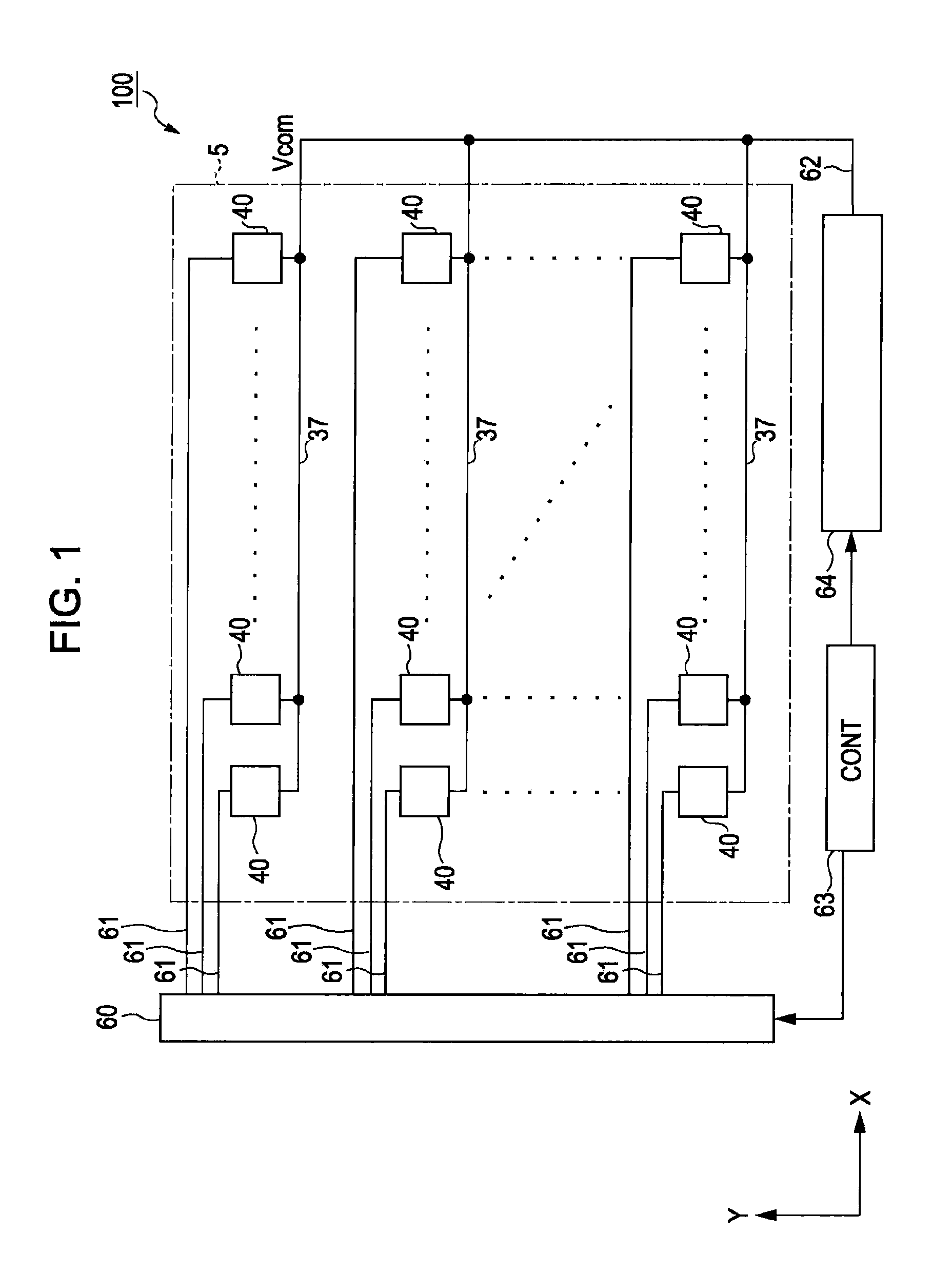
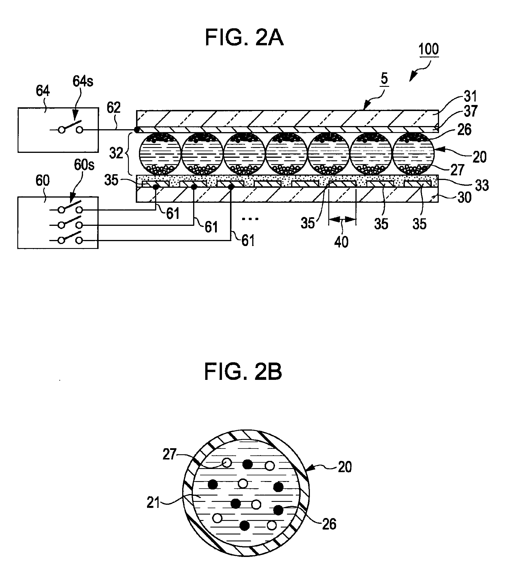
[0057]FIG. 1 is a schematic diagram illustrating an electrophoretic display apparatus 100 according to a first embodiment of the invention. FIG. 2A illustrates an electrical construction of the electrophoretic display apparatus 100 along with its cross-section.

[0058]The electrophoretic display apparatus 100 includes a display unit 5 in which a plurality of pixels (segments) 40 are disposed, a controller (control unit) 63, and a pixel electrode driving circuit 60 connected to the controller 63. The pixel electrode driving circuit 60 is connected to each of the pixels 40 via a pixel electrode wire line 61. The display unit 5 is provided with a common electrode 37 (refer to FIG. 2A) which is common to each of the pixels 40. In FIG. 1, the common electrode 37 is illustrated as a wire line for convenience.

[0059]The electrophoretic display apparatus 100 is a segment driving type electrophoretic display apparatus in which image data are transmitted from the controller 63 to the pixel elect...

embodiment 2

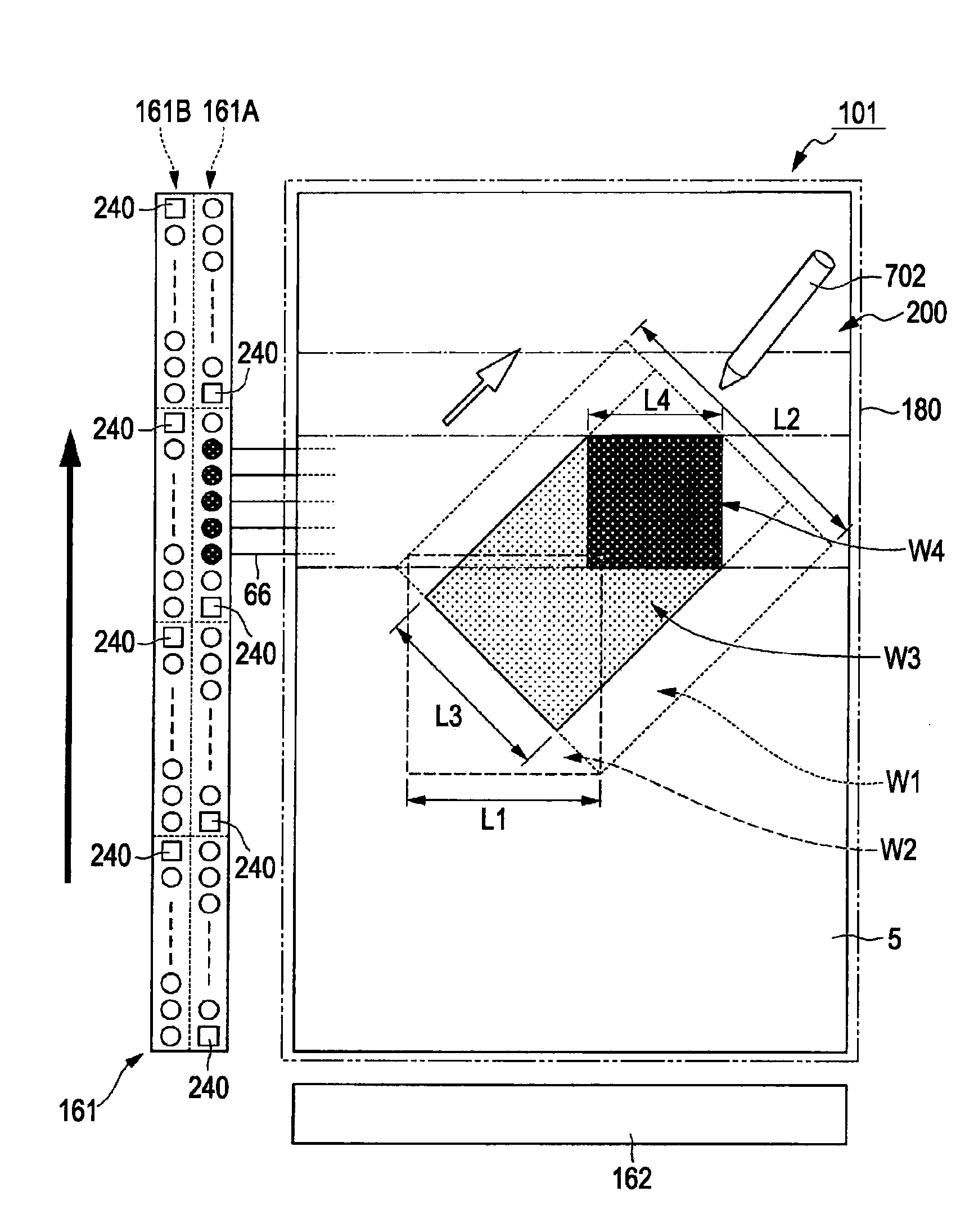
[0085]In the foregoing first embodiment of the invention, a case where a driving method according to the invention is applied to a segment type electrophoretic display apparatus has been described. A second embodiment of the invention relates to a driving method applied to an active matrix type electrophoretic display apparatus, which will now be described in more detail.

[0086]FIG. 5 illustrates a schematic construction of an electrophoretic display apparatus 200 according to a second embodiment of the invention. FIG. 6 illustrates a pixel circuit of an electrophoretic display apparatus 200 according to a second embodiment of the invention.

[0087]In FIGS. 5 and 6, like reference numerals denote like elements similar to those of the first embodiment, and their descriptions will be omitted.

[0088]Referring to FIG. 5, the electrophoretic display apparatus 200 includes a display unit 5 in which pixels 140 are arranged in a matrix shape, a scanning line driving circuit 161, a data line dri...


PUM

PropertyMeasurementUnit
grain diameteraaaaaaaaaa
Coulomb forceaaaaaaaaaa
electric fieldaaaaaaaaaa

Abstract

A method of driving an electrophoretic display apparatus, wherein during displaying an image on the display unit, executing a pixel electrode pulse driving in which a pulse periodically alternating between first and second potentials is input to the pixel electrode corresponding to the pixel of which a display state is changed, the first or second potential is input to the pixel electrode corresponding to the pixel of which a display state is not to be changed, and a potential equal to that of the pixel electrode corresponding to the pixel of which a display state is not to be changed is input to the common electrode.

Description

BACKGROUND[0001]1. Technical Field[0002]The present invention relates to a method of driving an electrophoretic display apparatus, an electrophoretic display apparatus, and an electronic device.[0003]2. Related Art[0004]A phenomenon in which electrophoretic particles migrate due to the Coulomb force when an electric field is applied to a dispersion liquid obtained by dispersing electrophoretic particles in a solution (so called electrophoresis) is known in the art. Electrophoretic display apparatuses using this phenomenon are being developed. For example, such electrophoretic display apparatuses are disclosed in JP-A-52-70791 and JPA-2003-140199.[0005]An electrophoretic display apparatus becomes able to change a display color into a desired color by generating a potential difference between a common electrode and a plurality of separated pixels. Meanwhile, as disclosed in JP-A-52-70791, a technique of maintaining a displayed color as it is without changing the display state at all b...

Claims


Application Information

Patent Timeline
Patent Type & Authority Applications(United States)
IPC IPC(8): G09G5/00G09G3/34G02F1/167
CPCG02F1/167G06F1/32G06F1/3265G06F3/14G09G3/344G09G5/363Y02B60/1242G09G2300/0847G09G2310/04G09G2310/06G09G2330/023G09G2380/14G09G2300/0426Y02D10/00
Inventor MIYAZAKI, ATSUSHI
Owner E INK CORPORATION
Why Eureka
Try Eureka