Image display apparatus and method of adjusting clock phase

a technology of image display and clock phase, which is applied in the direction of electrical apparatus, automatic control, instruments, etc., can solve the problems of inability to properly display images, manual adjustment of dot clock frequency, and high labor intensity and time-consuming for users to manually adjust the frequency of reproduced dot clocks, etc., and achieve automatic adjustment of phase

Inactive Publication Date: 2010-08-12
NEC DISPLAY SOLUTIONS LTD
View PDF20 Cites 8 Cited by
  • Summary
  • Abstract
  • Description
  • Claims
  • Application Information

AI Technical Summary

Benefits of technology

[0023]It is an object of the present invention to provide an image display apparatus which will solve the above problems and is capable of automatically adjusting the phase of a reproduced dot clock quickly.
[0025]If the video signal and the reproduced dot clock are brought out of phase with each other and the quality of a displayed image is degraded due to jitter, then the accumulated sums of the absolute values of the differential data become smaller. If the video signal and the reproduced dot clock are in substantial phase with each other, then the accumulated sums of the absolute values of the differential data become greater. When a delay for maximizing the accumulated sum of the absolute values of the differential data is given, the phase of the reproduced dot clock is adjusted correctly. The image display apparatus according to the first aspect of the invention prevents the image quality from being degraded due to a phase shift between the video signal and the reproduced dot clock by judging the delay for maximizing the accumulated sum of the absolute values of the differential data, as an optimum delay.
[0029]According to the present invention, as described above, since an optimum delay can be determined only by evaluating one frame of image, the phase of the reproduced dot block can be adjusted extremely quickly.

Problems solved by technology

Since the image display apparatus cannot acquire, in advance, the dot clock frequency (or the frequency-division ratio) in the video signal source, there is no guarantee that the frequency-division ratio of the frequency divider of the PLL circuit will be set to a correct value.
If the frequency-division ratio is not set to a correct value, then since the frequency of the reproduced dot clock is not in agreement with the frequency of the dot clock in the video signal source, a deviation occurs between the reproduced dot clock for capturing the video signal and the video signal, with the result that the image cannot properly be displayed.
However, it is highly tedious and time-consuming for the user to manually adjust the frequency of the reproduced dot clock.
However, even when the frequency of the reproduced dot clock is accurately adjusted, if the phase of the video signal and the reproduced dot clock is not properly adjusted, then the display image suffers fluctuation and flickering.
Since a tradeoff generally exists between jitter and response speed, it is difficult to eliminate jitter.
Since the reproduced dot clock suffers jitter of necessity, even when the frequency of the reproduced dot clock is in agreement with the frequency of the dot clock in the video signal source, if the phase of the reproduced dot clock is not correct, then it is difficult to display the image stably.
If the video signal and the reproduced dot clock are out of phase with each other, then the example shown in FIG. 2 occurs, and the sampled image becomes indefinite, resulting in a reduction in the displayed image quality.
However, the disclosed dot clock reproducing apparatus disclosed in Patent Document 1 evaluates phase adjustment for each frame, and hence requires time-consuming processing because it needs to evaluate phase adjustment for several frames to several tens of frames in order to determine an optimum value for phase adjustment.
However, if a very long cable which is not up to given standards is used to interconnect the video signal source and the image display apparatus or if the layout of components in the image display apparatus, i.e., the pattern of signal lines for transmitting a video signal and a dot clock, is not appropriate, then the dot clock and the digital video signal may possibly be out of phase with each other.

Method used


Image

  • Image display apparatus and method of adjusting clock phase
  • Image display apparatus and method of adjusting clock phase
  • Image display apparatus and method of adjusting clock phase

Examples


Embodiment Construction

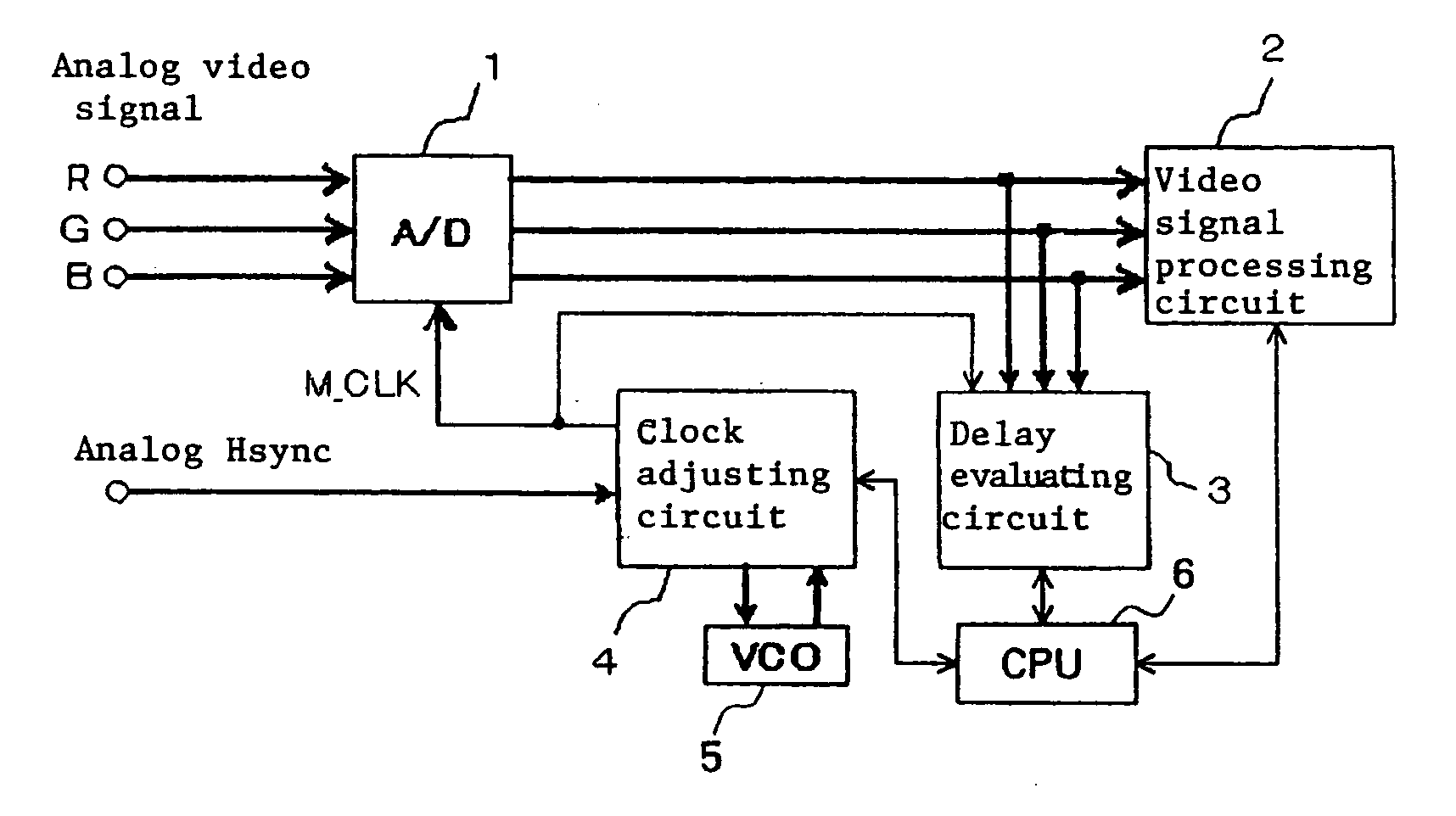
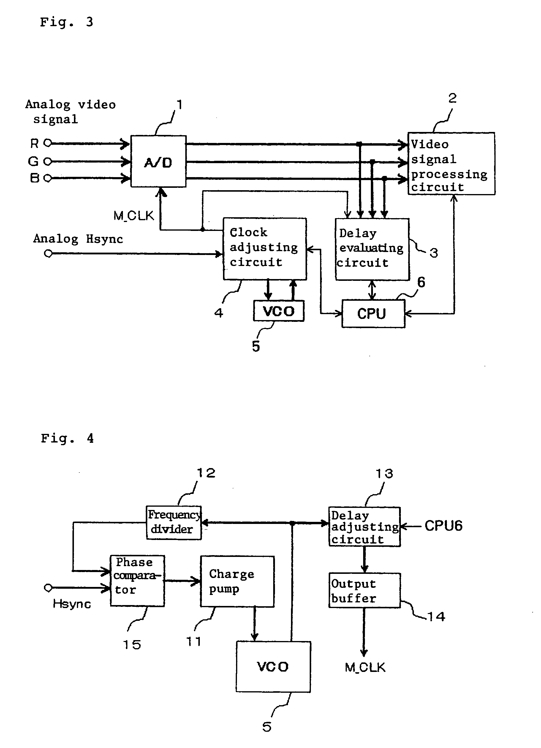
[0043]FIG. 3 shows in block form a general arrangement of an image display apparatus according to an embodiment of the present invention. The image display apparatus has a display device, not shown, employing a grid-like matrix of display elements, such as a liquid crystal panel display, a plasma display, an EL display, or the like. The image display apparatus also has circuits for displaying an image on the display device based on an analog video signal supplied from an external source. The circuits include A / D converter 1, video signal processing circuit 2, delay evaluating circuit 3, clock adjusting circuit 4, VCO (Voltage-Controlled Oscillator) 5, and CPU (Central Processing Unit) 7. Though not shown in FIG. 3, the image display apparatus also has a function to adjust the frequency of a reproduced dot clock. The frequency adjusting function is an existing frequency adjusting function such as the frequency adjusting function disclosed in Patent Document 2 referred to above.

[0044]...


PUM


Abstract

An image display apparatus includes a controller for dividing at least a portion of an image displayed based on a digital video signal, into a plurality of image areas defined by display lines, and establishing different delays for the divided image areas, a clock adjuster generating a clock in synchronism with the dot clock, delaying a phase of the clock according to the delays established by the controller, for the respective divided image areas, and outputting the delayed clock as the reproduced dot clock, and a delay evaluating unit converting differential data between adjacent signal levels into absolute values and accumulatively adding the absolute values based on the reproduced dot clock output from the clock adjuster, with respect to the display lines which define the divided image areas, thereby producing accumulated sums. The controller judges the delay established for the divided area with the maximum accumulated sum, as optimum.

Description

[0001]The present Application is a Divisional Application of U.S. patent application Ser. No. 11 / 798,579, filed on May 15, 2007, which is based on and claims priority from Japanese Patent Application No. 2006-181437, filed on Jun. 30, 2006, the entire contents of which are incorporated herein by reference.BACKGROUND OF THE INVENTION[0002]1. Field of the Invention[0003]The present invention relates to an image display apparatus employing a grid-like matrix of display elements, such as a liquid crystal panel display, a plasma display, an EL display, or the like, and more particularly to an image display apparatus to be connected to a video signal source for outputting a video signal such as an RGB video signal and a high-definition video signal.[0004]2. Description of the Related Art[0005]There are known image display apparatus employing a grid-like matrix of display elements, such as a liquid crystal panel display or the like.[0006]The image display apparatus of the above type is con...

Claims


Application Information

Patent Timeline
Patent Type & Authority Applications(United States)
IPC IPC(8): H03L7/00
CPCG09G5/008H03L7/18H03L7/08
Inventor KAWANA, TOSHIYUKINISHIDA, MICHIYA
Owner NEC DISPLAY SOLUTIONS LTD
Why Eureka
Try Eureka