In-cabin room projection for aircraft

a technology for aircraft and in-cabin rooms, which is applied in the direction of projectors, instruments, optics, etc., can solve the problems of large installation space, comparatively heavy, and light displays, and achieve the effect of easy installation and high energy efficiency

Inactive Publication Date: 2010-08-12
AIRBUS OPERATIONS GMBH
View PDF8 Cites 13 Cited by
  • Summary
  • Abstract
  • Description
  • Claims
  • Application Information

AI Technical Summary

Benefits of technology

[0011]This is a retractable projection surface that occupies minimal structural space in the retracted state. In addition, the projection surface has a very simple mechanism that has a low susceptibility to defects and a low weight. The mechanical projection surface is very reliable with respect to its operation and normally does not have to be serviced.
[0013]This may provide for simplified projection of image data in an aircraft that requires a comparatively small installation space.
[0019]The stability of the projection surface may be ensured in this fashion.
[0023]The projector consists, for example, of a very compact LED projector that has the size of a matchbox and a weight of approximately 50 g, wherein this projector is also highly energy efficient (power consumption approximately 3-5 Watt). The projector therefore can be easily installed into a control panel that is arranged, for example, above the passenger seat (so-called Passenger Service Unit, PSU).
[0024]Due to the inventive unrolling and rolling-up method, the mechanical projection surface is also very light and compact and therefore suitable for the invisible integration into the passenger service channel.

Problems solved by technology

The displays are luminous, but may be comparatively heavy and may require a large installation space.

Method used


Image

  • In-cabin room projection for aircraft
  • In-cabin room projection for aircraft
  • In-cabin room projection for aircraft

Examples


Embodiment Construction

[0040]The figures show schematic illustrations that are not true-to-scale. In the following description of the figures, the same reference symbols are used for identical or similar elements.

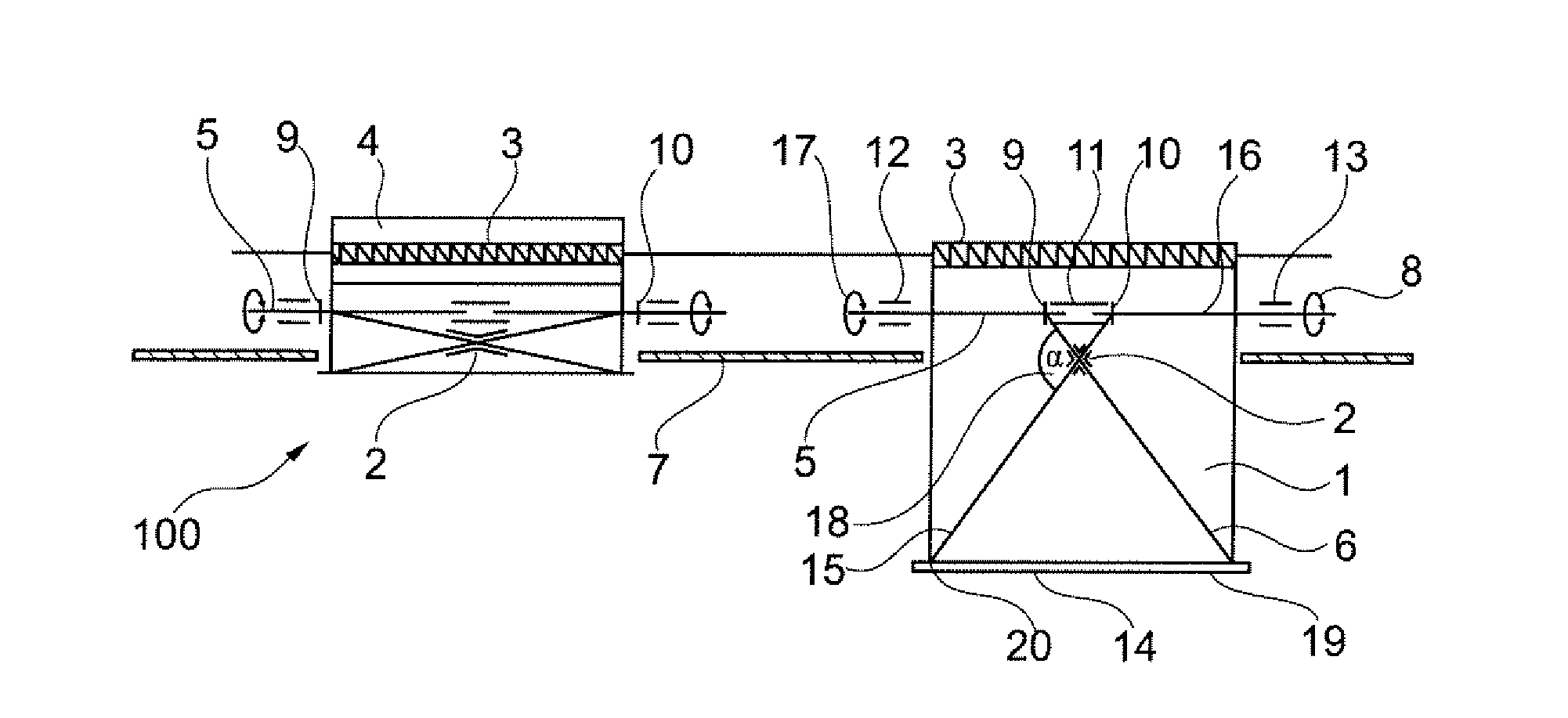
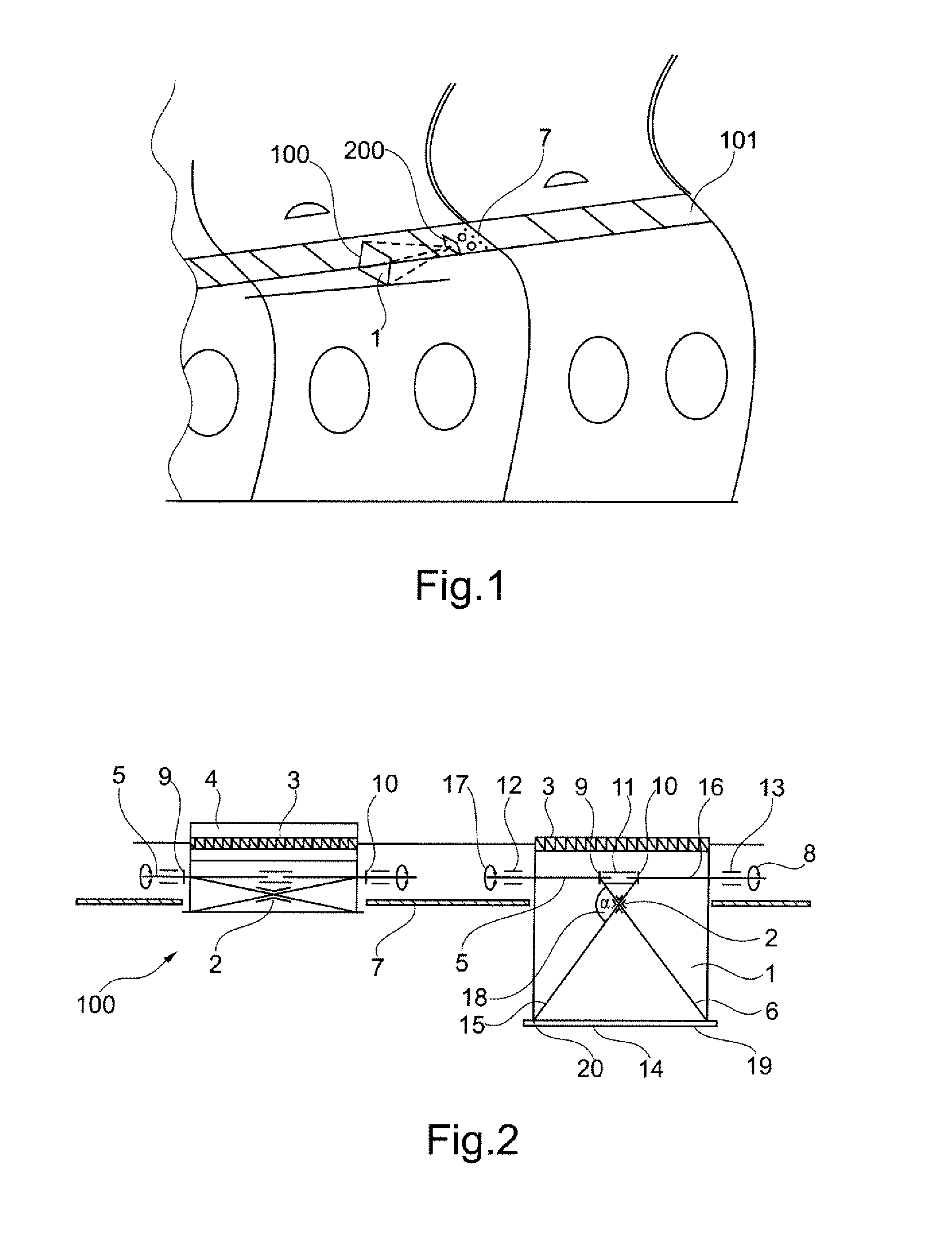
[0041]FIG. 1 shows a detail of an aircraft cabin with a passenger service channel 101, into which several PSUs 7 are integrated. In addition to lighting and control elements, each of the PSUs 7 features an integrated projector 200, as well as an integrated mechanical projection surface 100 with a projection screen 1.

[0042]It is naturally also possible to integrate the projector into a first interior furnishing element (for example a first PSU, a wall element or a ceiling element) and to integrate the projection surface 100 into a second interior furnishing element (for example a second PSU or a cover panel for the passenger service channel 101 or another wall element or ceiling element).

[0043]The projection surface 100 is realized in the form of a compact, fully automated projection screen that i...


PUM


Abstract

The invention pertains to the projection of image contents in an aircraft. A mechanical projection surface is provided that features a gear with two thrust sleeves and two gear rods. The two thrust sleeves are displaced opposite to one another due to the rotation of a threaded rod. Each of the two thrust sleeves carries along an assigned gear rod such that a projection screen is respectively retracted or extended.

Description

CROSS-REFERENCE TO RELATED APPLICATIONS[0001]This application claims the benefit of the filing date of U.S. Provisional Patent Application No. 61 / 207,382 filed Feb. 11, 2009, the disclosure of which application is hereby incorporated herein by reference.BACKGROUND OF THE INVENTION[0002]The invention pertains to the in-cabin room projection in aircraft. The invention particularly pertains to a mechanical projection surface for a projection system for an aircraft, a projection system with a mechanical projection surface, an aircraft, a method for extending a mechanical projection surface of a projection system, as well as a method for retracting the projection surface.[0003]In commercial aircraft and, in particular, in long-range aircraft, it is desirable to design the cabin in such a way that the stay on board the aircraft is as pleasant as possible for the passengers. Projectors may be used for this purpose in order to provide the passengers, for example, with optical information.[0...

Claims


Application Information

Patent Timeline
Patent Type & Authority Applications(United States)
IPC IPC(8): G03B21/58
CPCG03B21/58
Inventor BUDINGER, TILOSCHMITZ, GUENTER
Owner AIRBUS OPERATIONS GMBH
Why Eureka
Try Eureka