System and method for improved spur reduction in direct RF receiver architectures

a linearity technology, applied in the direction of digital transmission, amplitude demodulation, pulse technique, etc., can solve the problems of non-desired spurious artifacts and spread in the frequency domain, and achieve the effect of improving the linearity of direct radio frequency (rf) receiver architecture, reducing spurious artifacts, and increasing spur-free dynamic rang

Inactive Publication Date: 2010-08-12
L 3 COMM INTEGRATED SYST
View PDF24 Cites 18 Cited by
  • Summary
  • Abstract
  • Description
  • Claims
  • Application Information

AI Technical Summary

Benefits of technology

[0012]The systems and methods disclosed herein provide improved spur reduction architectures that improve linearity in direct radio frequency (RF) receiver architectures. Non-uniform sampling in the form of sampling clock phase (or frequency) modulation is used to induce phase (or frequency) modulation on signals that are being received from a given Nyquist zone. In this context, the Nyquist zone is defined by integer multiples of Fs / 2, where Fs is the average RF sample rate. At the output of the ADC (analog-to-digital converter), the signals are de-modulated to remove the induced modulation based on the Nyquist zone that is being received. Non-desired interfering signals from a non-desired Nyquist zone that leak past the anti-aliasing filter as well as many ADC spurs have a different induced modulation than desired signals from the given Nyquist zone. The de-modulation process results in these non-desired spurious artifacts (interfering leakage signals and ADC spurs) being spread in the frequency domain. For the case of strong spurious artifacts, the artifact can be removed after measuring the induced modulation and de-modulating. For the case of weak spurious artifacts, the de-modulation for the desired Nyquist zone will spread these signals in the frequency domain. In either case, increased spur-free dynamic range is achieved, where these un-desired artifacts or interfering leakage signals are treated as spurs. As an additional minor benefit, the induced modulation on signals also provides a dithering effect on the ADC, Thus, quantization spurs and related spurs caused by sampling a pure sinusoid are removed or reduced similar to conventional dithering techniques.

Problems solved by technology

The de-modulation process results in these non-desired spurious artifacts (interfering leakage signals and ADC spurs) being spread in the frequency domain.

Method used


Image

  • System and method for improved spur reduction in direct RF receiver architectures
  • System and method for improved spur reduction in direct RF receiver architectures
  • System and method for improved spur reduction in direct RF receiver architectures

Examples


Embodiment Construction

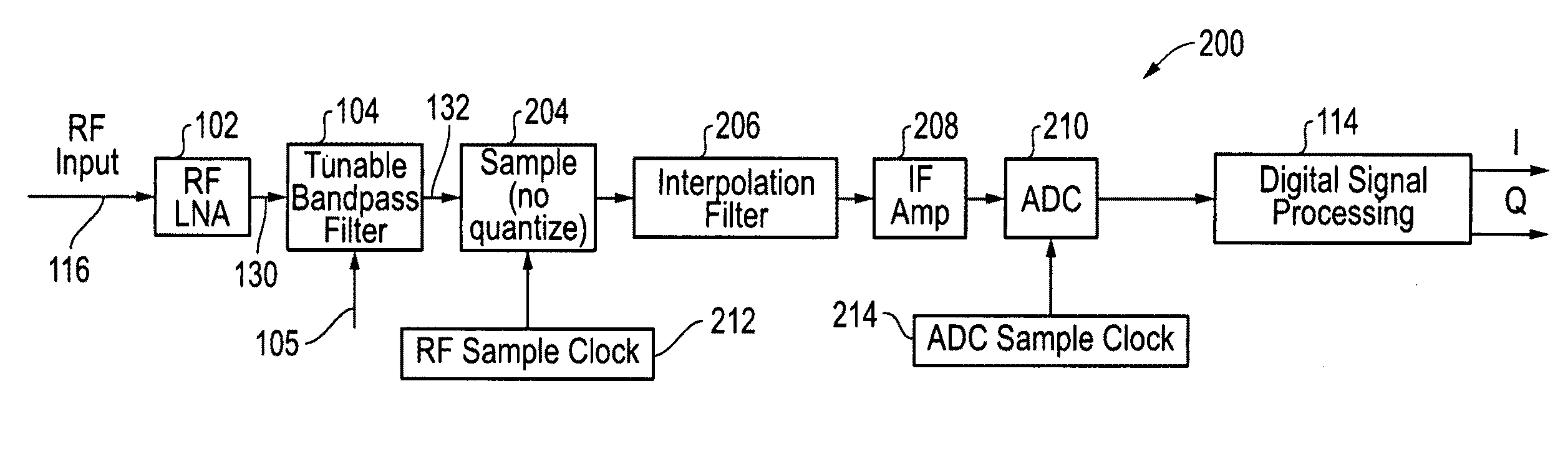
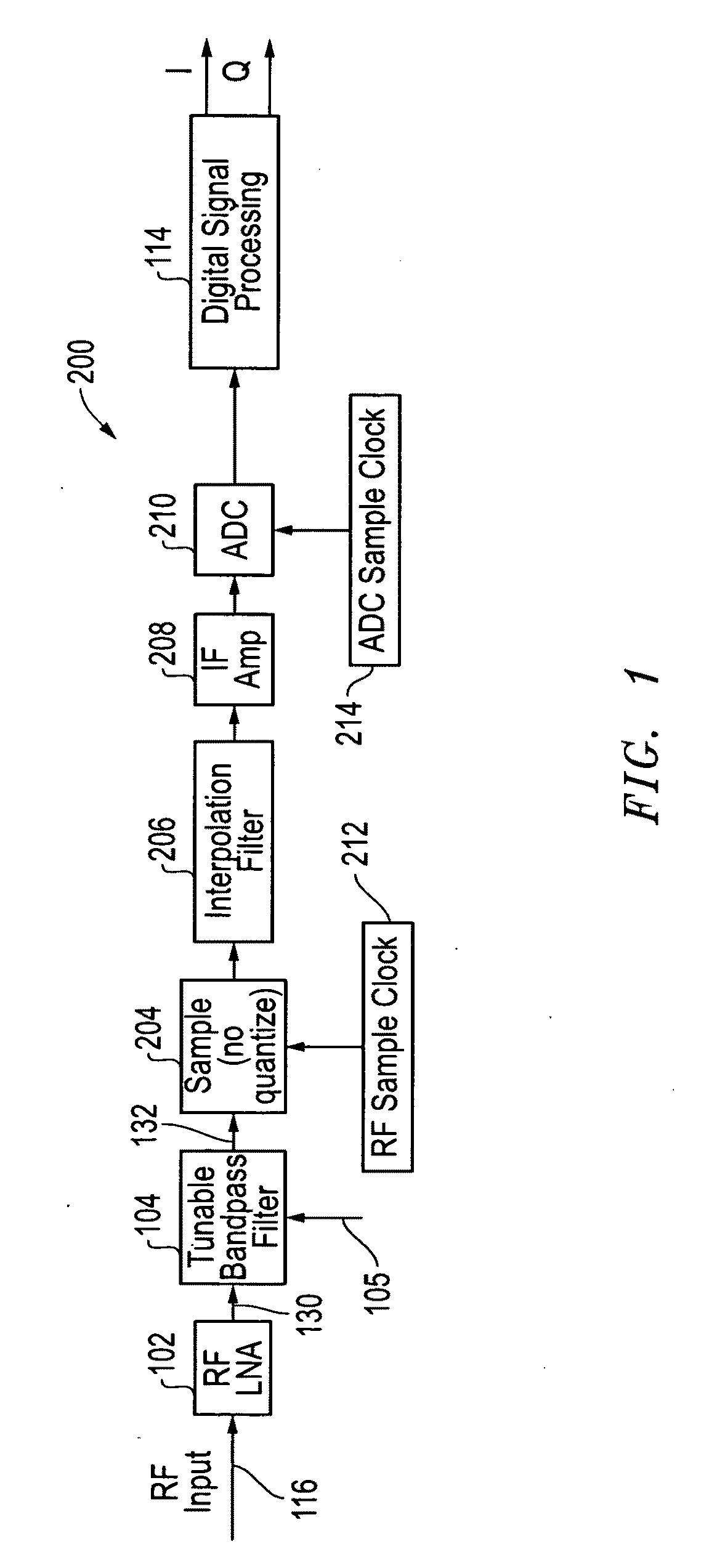
[0023]The systems and methods disclosed herein provide improved spur reduction architectures that reduce spurs and improve linearity in direct radio frequency (RF) receiver architectures. As described further below, these spur reduction architectures described herein provide improved receiver performance. For example, the architectures improve receiver performance by providing reductions of certain types of spurs, such as ADC tonal spurs, thereby making the receiver operation more linear. The architectures also ease requirements for anti-alias filters, particularly those used in bandpass sampling receivers, due to improved out-of-band rejection thereby making the receiver operation more linear with respect to desired band. And the architectures in effect perform a type of signal dithering thereby improving the linearity of the receiver ADC processing. These spur reduction and linearity improvements result from inducing a different modulation on non-desired leakage interfering signal...


PUM


Abstract

Improved spur reduction architectures that improve linearity in direct radio frequency (RF) receiver architectures. Non-uniform sampling in the form of sampling clock phase (or frequency) modulation is used to induce phase (or frequency) modulation on signals that are being received from a given Nyquist zone. At the output of the ADC (analog-to-digital converter), the signals are de-modulated to remove the induced modulation based on the Nyquist zone that is being received. The de-modulation process results in non-desired spurious artifacts (interfering leakage signals and ADC spurs) being spread in the frequency domain. Strong spurious artifacts may be removed after measuring the induced modulation and de-modulating. For the case of weak spurious artifacts, the de-modulation for the desired Nyquist zone spread these signals in the frequency domain. Induced modulation on signals may also provide a dithering effect on the ADC.

Description

RELATED APPLICATIONS [0001]The present application claims priority to co-pending U.S. provisional patent application Ser. No. 61 / 203,115 filed Dec. 18, 2008 and entitled “SYSTEM AND METHOD FOR IMPROVED SPUR REDUCTION IN DIRECT RF RECEIVER ARCHITECTURES”, by Fudge et al., the disclosure of which is incorporated herein by reference in its entirety.[0002]The present provisional application is related in subject matter to concurrently filed patent application Ser. No. ______ entitled “SYSTEM AND METHOD FOR CLOCK JITTER COMPENSATION IN DIRECT RF RECEIVER ARCHITECTURES” by Fudge et al., which is incorporated herein by reference in its entirety, and to Provisional Patent Application Ser. No. 61 / 203,114 filed Dec. 18, 2008 and entitled “SYSTEM AND METHOD FOR CLOCK JITTER COMPENSATION IN DIRECT RF RECEIVER ARCHITECTURES” by Fudge et al., which is also incorporated herein by reference in its entirety.TECHNICAL FIELD OF THE INVENTION [0003]This invention relates to receiver and transmitter arc...

Claims


Application Information

Patent Timeline
Patent Type & Authority Applications(United States)
IPC IPC(8): H04L27/14H04L27/00
CPCH04L27/1566H04L27/148
Inventor FUDGE, GERALD L.BLAND, ROSS E.RAVINDRAN, SUJITCHIVERS, MARK A.
Owner L 3 COMM INTEGRATED SYST
Why Eureka
Try Eureka