Joint connector and wire short-circuiting method using the same

Active Publication Date: 2010-08-12
AUTONETWORKS TECH LTD +2
View PDF6 Cites 10 Cited by
  • Summary
  • Abstract
  • Description
  • Claims
  • Application Information

AI Technical Summary

Benefits of technology

[0013]In the present invention, the use of the deflection of each of the terminal locking pieces formed in the connector housing of the joint connector enables an insertion state of each of the wire-side terminals in the connector ho

Problems solved by technology

However, the above conventional joint connector has a problem in its inspection.
Reliable mutual short-circuit of a plurality of electric wires by use of the joint connector requires an inspection of an insertion state of the wire-side terminals in the connector housing of the joint connector; however, the joint terminal of the joint connector is located at a deepmost position

Method used


Image

  • Joint connector and wire short-circuiting method using the same
  • Joint connector and wire short-circuiting method using the same
  • Joint connector and wire short-circuiting method using the same

Examples


Embodiment Construction

[0035]With reference to the drawings, the present invention will be described based on a preferred embodiment thereof.

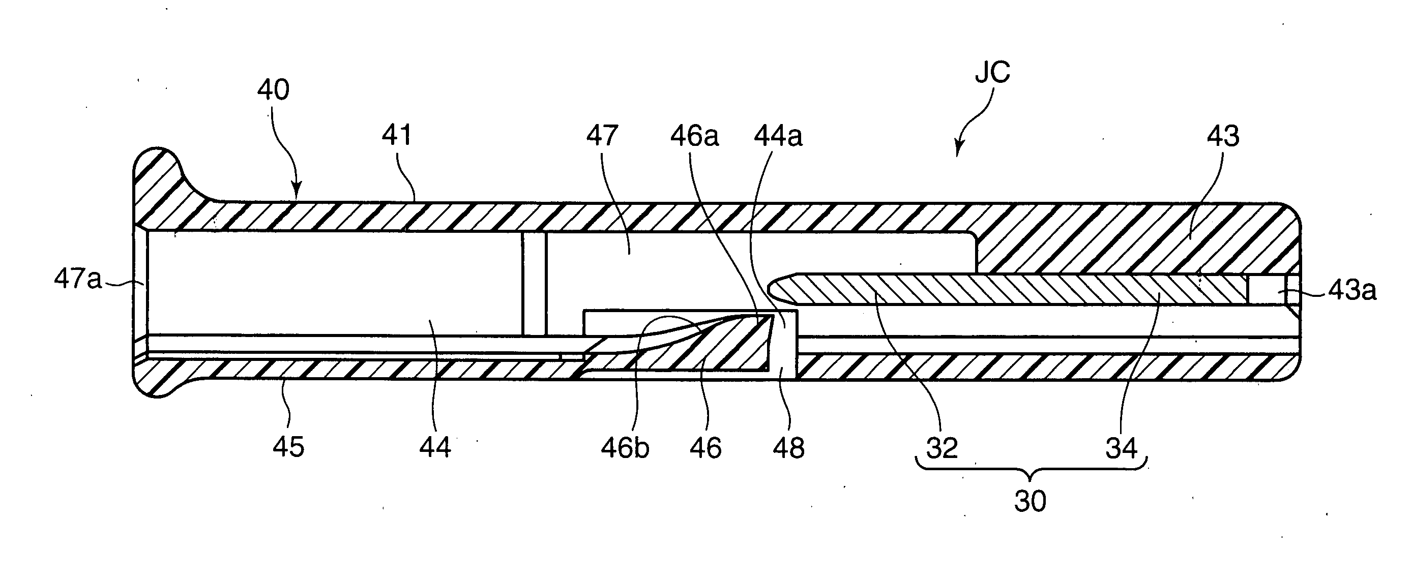
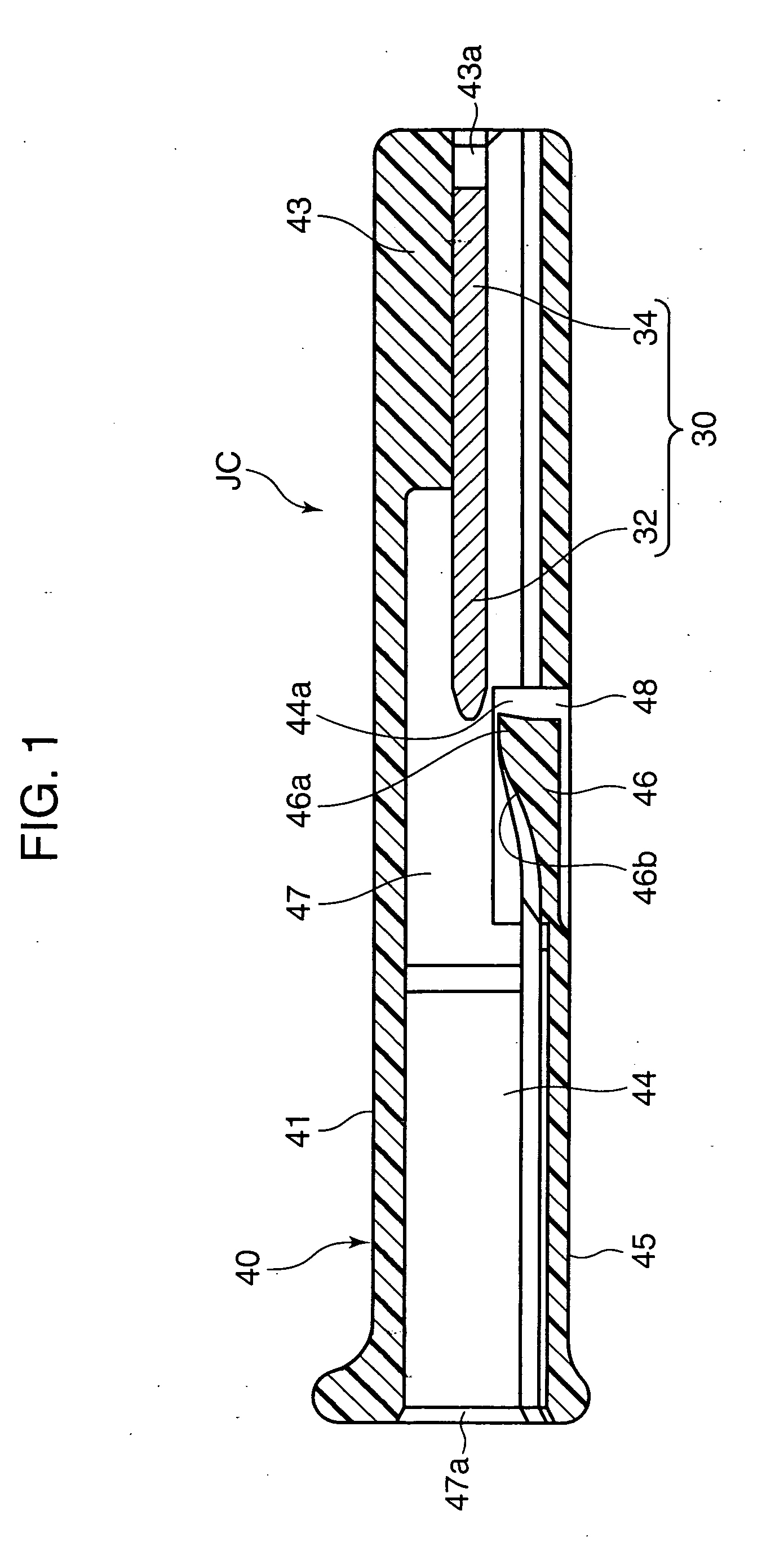
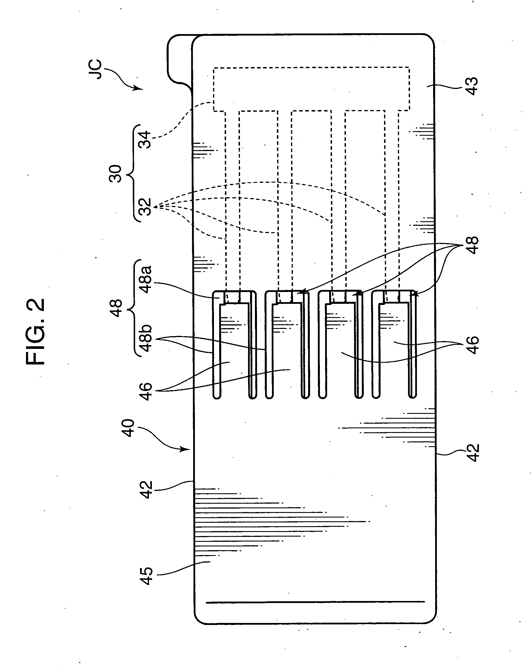
[0036]FIGS. 1 to 5 show a joint connector JC according to a first embodiment of the present invention. The joint connector JC is designed to mutually short-circuit a plurality of wire-side terminals 20 each provided on an end of each of a plurality of (in the first embodiment, four) electric wires 10 illustrated in FIGS. 6 to 8.

[0037]Each of the wires 10 comprises a conductor and an insulating sheath covering the conductor, having an end in which the insulating sheath is removed to expose the conductor, onto which the wire-side terminal 20 is crimped.

[0038]The wire-side terminal 20 in the first embodiment, which is formed by bending a single metal plate, has a female-type electric contact section 22 and a wire-crimping section 24, which are axially arranged on respective front and rear sides.

[0039]The electric contact section 22 has a hollow angular tube-shaped main ...


PUM


Abstract

A joint connector capable of mutually short-circuiting wires reliably without an increase in the number of components and size thereof. The joint connector (JC) comprises a joint terminal for short-circuiting and a connector housing. The joint terminal includes a plurality of electric contact portions and a short-circuiting portion connecting the electric contact portions. The connector housing has a bottom wall and other walls surrounding a terminal insertion space into which each of the wire-side terminal is inserted, and a lance for locking the inserted wire-side terminal. The lance adapted to be deflected so as to project outwardly from the bottom wall, until the wire-side terminal reaches a proper insertion depth position, to be retracted from the wire-side terminal, and elastically return into the bottom wall, when the wire-side terminal reaches the position. The deflection of the lance allows the insertion of the wire-side terminal to be checked.

Description

TECHNICAL FIELD[0001]The present invention relates to a joint connector designed to be used, in an automobile wire harness and others, to mutually electrically short-circuit a plurality of wire-side terminals provided on respective ends of electric wires for forming a branch circuit or the like, and a wire short-circuiting method using the joint connector.BACKGROUND ART[0002]Heretofore, as the above type of joint connector, there has been known one disclosed in the following Patent Document 1. This connector comprises a joint terminal and a connector housing (connector housing) holding the joint terminal.[0003]The joint terminal is to mutually short-circuit a plurality of wire-side terminals each provided on an end of each of a plurality of electric wires, integrally having a plurality of electric contact portions and a connection portion. The electric contact portions are arranged in a specific direction, and connected to each other through the connection portion. Each of the elect...

Claims


Application Information

Patent Timeline
IPC IPC(8): H01R31/08G01R31/04
CPCH01R13/4223H01R4/185H01R13/11H01R31/08H01R2201/26
Inventor OMORI, YASUOHIRAI, HIROKITANAKA, TETSUJITAMAGAWA, TATSUO
Owner AUTONETWORKS TECH LTD
Why Eureka
Try Eureka