
Method for detecting line-to-line fault location in power network

a technology of power network and fault location, applied in fault location, testing circuits, instruments, etc., can solve the problems of large power system scale, many kinds of faults, and the above conventional method cannot be applied to a balanced network, so as to simplify matrix inversion calculations, the effect of easy and accurate determination

Inactive Publication Date: 2006-01-17
MYONGJI UNIVERSITY
View PDF8 Cites 6 Cited by
  • Summary
  • Abstract
  • Description
  • Claims
  • Application Information

AI Technical Summary

Benefits of technology

"The present invention provides a method for detecting a line-to-line fault location in a power network using direct 3-phase circuit analysis. This method does not require the use of symmetrical component transformation and can easily and accurately determine the location of a fault in both balanced and unbalanced networks. The method involves determining elements of a line impedance matrix and a load impedance matrix, and phase voltages and currents at a relay, and then using these elements to calculate a line-to-line fault distance. The method is derived from a model based on the phase voltage and current, the line impedance matrix, and the fault current. The use of the matrix inverse lemma simplifies the calculation of the inverse matrix and the fault location equation. Overall, the method provides a more efficient and accurate way to detect line-to-line faults in power networks."

Problems solved by technology

Rapid growth of economy has resulted in large scale of power systems, and an excessive increase in transmission and distribution networks of electric power systems causes many kinds of faults by various causes.
However, because most of lines are exposed to air, lightning, contact of animals or mal-functioning of protection devices causes many kinds of faults.
However, the above conventional method can only be applied to a balanced network, because the simplified equations of zero sequence, positive sequence and negative sequence, which are not correlated, can be obtained by symmetrical component transformation only in the balanced network.
Thus, the conventional method is not available for unbalanced systems.

Method used


Image

  • Method for detecting line-to-line fault location in power network
  • Method for detecting line-to-line fault location in power network
  • Method for detecting line-to-line fault location in power network

Examples


Embodiment Construction

[0026]Preferred embodiment of the present invention will now be described in detail, with reference to the accompanying drawings.

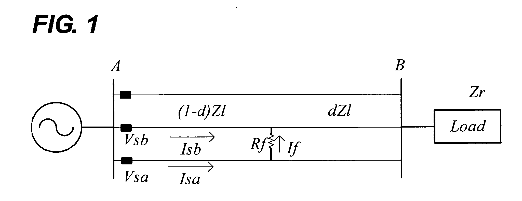
[0027]FIG. 1 shows general 3-phase transmission and distribution of simplified diagram of faulted network whether they are operated in a balance or unbalance manner. The proposed algorithm use voltages and currents measured at a relay.

[0028]Based on a model shown in FIG. 1 and assuming the capacitance of lines negligible, phase voltages and phase currents at the location of relay A satisfy the following model equation.

VSa−VSb=(1−d)((Zlaa−Zlba)Isb+(Zlac−Zlbb)Isb +(Zlac−Zlcb)+IfRf  (1)

[0029]Where, VSa and VSb are phase voltages of a-phase and b-phase respectively, and ISa, ISb and ISc are phase currents of a-phase, b-phase and c-phase respectively at the relay A, ISabc=[ISa ISb ISc]′ is a phase current vector at the relay A, Zlabc=[ZlaaZlabZlacZlbaZlbbZlbcZlcaZlcbZlcc]

represents a line impedance matrix, If represents a fault current, Rf is a fault resistance...


PUM


Abstract

The present invention relates to a method for detecting a line-to-line fault location in power network, and more particularly, detecting the line-to-line fault location by direct 3-phase circuit analysis without using a symmetrical component transformation, so even in an unbalanced 3-phase circuit, the line-to-line fault location can be accurately detected. In the method using direct 3-phase circuit analysis of this invention, inverse lemma is used to simplify matrix inversion calculations, thus the line-to-line fault location can be easily and accurately determined even in the case of an unbalanced network without symmetrical component transformation.

Description

BACKGROUND OF THE INVENTION[0001](a) Field of the Invention[0002]The present invention relates to a method for detecting a line-to-line fault location in power network, and more particularly, detecting the line-to-line fault location with direct 3-phase circuit analysis without using a symmetrical component transformation, whereby even in an unbalanced 3-phase circuit the line-to-line fault location can be accurately detected.[0003](b) Description of the Related Art[0004]Rapid growth of economy has resulted in large scale of power systems, and an excessive increase in transmission and distribution networks of electric power systems causes many kinds of faults by various causes. Transmission and distribution networks of electric power systems are playing very important roles as the links between the power suppliers and the consumers. However, because most of lines are exposed to air, lightning, contact of animals or mal-functioning of protection devices causes many kinds of faults. W...

Claims


Application Information

Patent Timeline
Patent Type & Authority Patents(United States)
IPC IPC(8): G01R31/00G01R31/14G01R31/08H02H1/00H02H3/40
CPCG01R31/088H02H3/40H02H1/0092
Inventor CHOI, MYOEN-SONGLEE, SEUNG-JAE
Owner MYONGJI UNIVERSITY
Learn More