Motor Inspection Method

Inactive Publication Date: 2006-09-21
NIDEC CORP
View PDF3 Cites 6 Cited by
  • Summary
  • Abstract
  • Description
  • Claims
  • Application Information

AI Technical Summary

Benefits of technology

[0018] In the method according to the invention, the data are collected during normal rotation mode of about one rotation, and therefore the measurement can be completed within a very short length of time. This invention is applicable, therefore, to a spindle motor for a hard disk to rotate a small-diameter disk, which spindle motor has a small moment of inertia around the rotat

Problems solved by technology

In the process, fine damages, distortion or dust is liable to occur, thereby leading to the disadvantage that this measuring method cannot be used for the motor for precision equipments or the rotor fabricated of a fragile material.
In the case where the moment of inertia around the rotational axis is small, however, a large ratio of the effects of various losses immediately changes the rotational speed, and therefore the counter-electromotive force dependent to a large measure on the rotational spe

Method used


Image

  • Motor Inspection Method
  • Motor Inspection Method
  • Motor Inspection Method

Examples


first embodiment

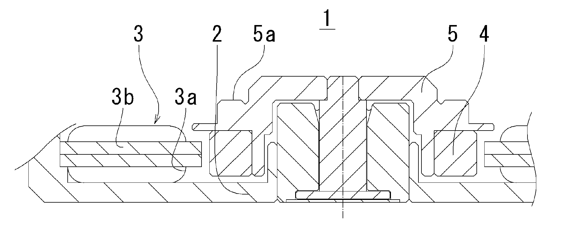
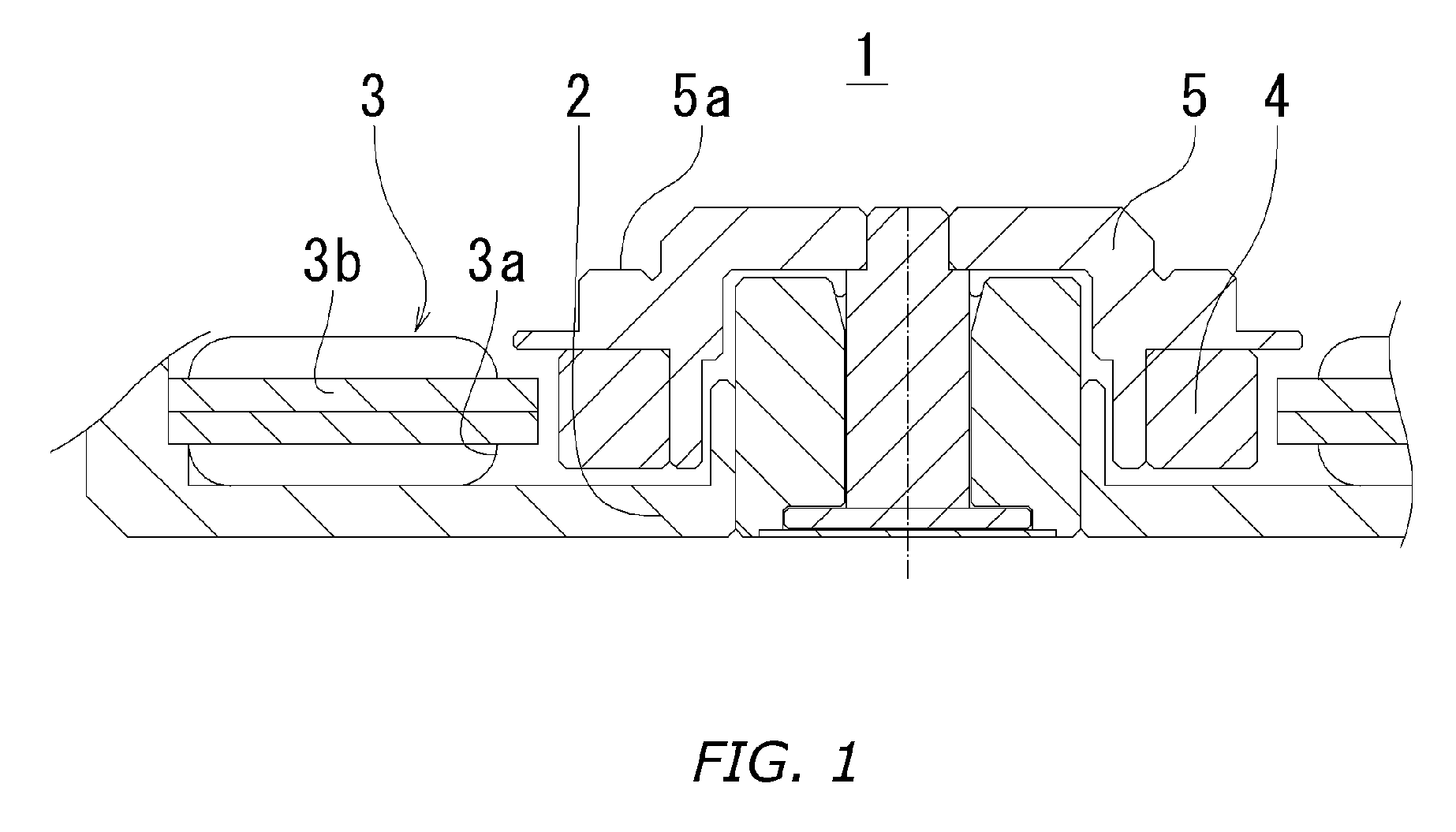
[0026] As an inspection method according to a first embodiment of the invention, a method of inspecting a spindle motor for a hard disk is explained. FIG. 1 shows the spindle motor for the hard disk according to this embodiment.

[0027] 1-1 Configuration of Spindle Motor

[0028] The spindle motor 1 is a DC brushless motor including a stator 3 having a plurality of magnetic pole teeth 3a. The magnetic pole teeth 3a are wound with coils 3b, the ends of which are connected to a drive circuit for controlling the current supplied to the coils 3b. The stator 3 is fixed on a base 2 of the spindle motor 1. An annular rotor magnet 4 is mounted at a position in diametrically opposed relation to the magnetic pole teeth 3a of the stator 3. The rotor magnet 4 is a permanent magnet with a plurality of magnetic poles magnetized to generate a magnetic field. The rotor magnet 4 is mounted on a rotor hub 5 constituting a rotary member, and rotatably supported on the stator 3 through bearings. The beari...

second embodiment

[0063] Another inspection method according to a second embodiment of invention for the spindle motor 1 similar to the one used in the first embodiment is explained.

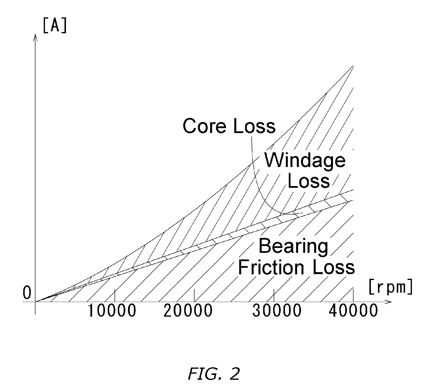
[0064] 2-1 Spindle Motor and Energy Loss Thereof.

The configuration of the spindle motor 1 according to this embodiment is similar to that of the first embodiment. The energy loss characteristic is also similar.

[0065] Based on the result of study made in a similar manner to the first embodiment, therefore, the deceleration function is set as a function primarily proportional to the rotational angular speed.

[0066] 2-2 Measurement of Counter-Electromotive Force and Rotational Position

[0067] The measurement of the counter-electromotive force according to this embodiment, like in the first embodiment, uses the spindle motor 1 to be measured and a device (such as the digital oscilloscope or voltmeter) capable of temporally measuring the terminal potential difference. In addition, the signal output from a device (such as a...


PUM


Abstract

A method of measuring the counter-electromotive force of the motor accurately is disclosed. The counter-electromotive force of the motor changes with the rotational position and the rotational speed. The value of the counter-electromotive force measured during the inertial rotation is a value associated the simultaneous change of the rotational position and the rotational speed and required to be corrected. The change rate of the rotational speed is set as a deceleration function, and the data are statistically processed using the measurement value of the counter-electromotive force at minuscule time intervals. In this way, the error elements are eliminated for each motor measured thereby to determine the corrected counter-electromotive force at a predetermined rotational speed. Even a miniature motor rapidly decreased in speed can be accurately measured within a short time.

Description

BACKGROUND OF THE INVENTION [0001] 1. Field of the Invention [0002] This invention relates to a method of inspecting the counter-electromotive force of a motor, or in particular to a method of correcting the measurement value of the counter-electromotive force generated across coils during the inertial rotation of the motor to the value of the counter-electromotive force generated at the time of the rotation at a predetermined rotational speed. [0003] 2. Description of the Related Art [0004] The motor is an indispensable energy converter in the current society, which makes possible the mutual conversion between the electric energy and the kinetic rotational energy. The motor of various sizes are available ranging from as small as several millimeters to as large as more than one meter in diameter and finds wide applications. In the field of information technology, for example, a miniature motor is used to rotate a discal recording medium. [0005] The motor is configured of a permanent...

Claims


Application Information

Patent Timeline
IPC IPC(8): G01R33/10G01R31/34H02P29/00
CPCG01R31/343H02P6/182
Inventor IGUCHI, TAKURO
Owner NIDEC CORP
Why Eureka
Try Eureka