Case Drain Line Pressure Switch With Automatic Fan Drive Motor Shutdown

a pressure switch and fan drive technology, applied in the direction of positive displacement liquid engines, piston pumps, fluid couplings, etc., can solve the problems of motor failure, complete draining of hydraulic fluid of the tractor, and the likelihood of motor damage is particularly acute, so as to effectively shut down the hydraulic motor

Inactive Publication Date: 2010-08-19
CNH IND AMERICA LLC
View PDF15 Cites 17 Cited by
  • Summary
  • Abstract
  • Description
  • Claims
  • Application Information

AI Technical Summary

Benefits of technology

[0007]The case drain circuit may also include an auxiliary fluid dump into which hydraulic fluid may be delivered during high pressure conditions in the case drain circuit. The fluid dump may include a float switch that is activated when the fluid level in the dump reaches a predetermined level. Activation of the float switch may also cause illumination of the in-cab light and / or sounding of the in-cab alarm. Moreover, the float switch may provide a corresponding signal to the controller for the solenoid that responsive thereto cuts current to the solenoid to effectively shutdown the hydraulic motor.

Problems solved by technology

If the connection between the male and female couplers is not made properly or if the connection is broken while the hydraulic motor is turning, the pressure in the case drain line can buildup, and quickly, resulting in motor failure.
The likelihood of damage to the motor is particularly acute since most bulk fill assemblies do not provide any audio or visual warning that the connection between the tractor and the bulk fill case drain lines is disconnected or has otherwise become broken.
One proposed solution is to dump fluid in the case drain line to atmosphere, but this is not environmentally preferred and can lead to a complete draining of hydraulic fluid of the tractor.

Method used


Image

  • Case Drain Line Pressure Switch With Automatic Fan Drive Motor Shutdown
  • Case Drain Line Pressure Switch With Automatic Fan Drive Motor Shutdown
  • Case Drain Line Pressure Switch With Automatic Fan Drive Motor Shutdown

Examples


Embodiment Construction

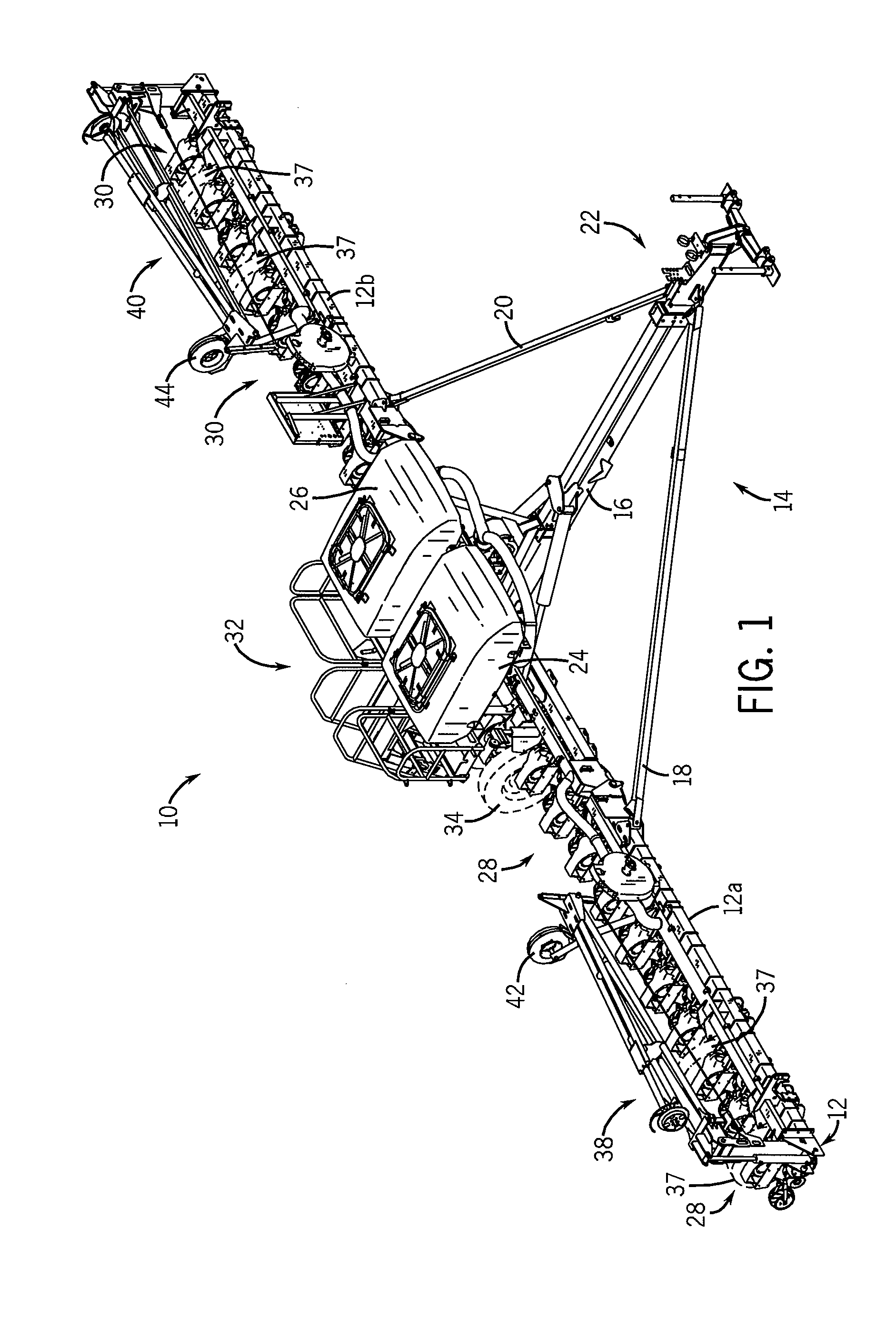
[0017]A planter 10 is shown inFIG. 1 and generally includes a frame 12 that extends generally transverse to a path of travel. The frame 12 carries a yoke 14 that includes a center beam 16 and a pair of support arms 18, 20. The center beam 16 and the support arms 18, 20 are connected to a hitch assembly 22 for coupling the planter 10 to a tractor (not shown) or similar towing vehicle.

[0018]The frame 12 also supports a pair of tanks 24, 26 that carry seed, fertilizer or other planting material to be deposited onto the planting surface. Planting material is fed from the tanks 24, 26 in a conventional manner using a metering subassembly (not shown) to two sets of row or dispensing units 28, 30, respectively. The row units 28, 30 are spaced linearly along the frame 12 and include a material dispensing port associated with a material hopper, furrow opener, and a packer wheel, as known in the art. One skilled in the art will appreciate that material is fed from the tanks 24, 26 to the indi...


PUM


Abstract

A case drain circuit particularly well suited for use with a bulk fill subassembly or a vacuum fan assembly of an agricultural implement towed by a tractor or similar vehicle includes a pressure switch that may cause illumination of an in-cab warning light and / or sounding of an in-cab alarm when pressure in the case drain circuit exceeds a predetermined threshold. A fan is driven by a solenoid controlled hydraulic motor which is supplied hydraulic fluid under pressure from a flow control valve to the motor in accordance with electrical signals that are supplied to the solenoid by a controller. The case drain circuit provides a pathway along which leakage fluid from the motor may be delivered to a fluid reservoir, preferably carried by the towing vehicle. During undesirable high pressure conditions in the case drain circuit, the pressure switch provides a corresponding high pressure signal to the controller that in turn cuts electrical current to the solenoid to cut the flow of hydraulic fluid to the motor.

Description

FIELD OF THE INVENTION[0001]The present invention relates generally to hydraulic systems for agricultural and construction implements and, more particularly, to a case drain circuit having a pressure switch that shuts down a fan drive motor, from which the case drain circuit receives leakage fluid, during undesirable pressure levels in the case drain circuit.FIELD OF THE INVENTION[0002]To improve efficiency many planters are equipped with a bulk fill subassembly. Commonly, a bulk fan drive will include two large tanks or hoppers that are mounted to the planter frame. The tanks are typically loaded with seed and metering systems deliver the seed from the tanks in a controlled manner to the individual seed units carried by the seeder. The metering systems commonly include, or are operable with, a fan assembly that produces an air stream in which product from the tanks is delivered to the individual seed units. In many setups, the bulk fill fan assembly is driven by a solenoid controll...

Claims


Application Information

Patent Timeline
Patent Type & Authority Applications(United States)
IPC IPC(8): F15B20/00F04D13/04F15B13/042
CPCF04D25/04A01C7/081
Inventor BETTIN, LEONARD A.STEFFENSEN, DARWIN
Owner CNH IND AMERICA LLC
Why Eureka
Try Eureka