Oscillation drive device, physical quantity measurement device and electronic apparatus

a drive device and drive circuit technology, applied in the direction of pulse manipulation, pulse technique, instruments, etc., can solve the problems of reducing the gyroscope is bulkier, and the capacitor area and resistance of the cr oscillation circuit becomes large, so as to reduce the size and power consumption of the electronic apparatus, and the oscillation startup time is short. , the effect of reliable oscillation

Inactive Publication Date: 2010-08-19
SEIKO EPSON CORP
View PDF4 Cites 56 Cited by
  • Summary
  • Abstract
  • Description
  • Claims
  • Application Information

AI Technical Summary

Benefits of technology

[0014]In accordance with some embodiments of the invention, it is possible to provide an oscillation drive device that can reliably oscillate, and shorten its oscillation startup time, and to provide a physical quantity measurement device and an electronic apparatus using the oscillation drive device.

Problems solved by technology

This causes a problem in that, when the vibrator is excited to generate a driving vibration, it needs a longer time (startup time) for a signal from the vibrator to stabilize.
However, according to the technology provided in Patent Document 1, if the vibrator is to be oscillated with a frequency that is close to the driving frequency of the crystal oscillator, the element area of capacitors and resistances of the CR oscillation circuit becomes large.
This brings about a problem which results in a bulkier vibration type gyroscope (vibration type gyro-sensor) and a higher cost.
Also, according to the technology provided in Patent Document 1, the vibrator is started initially with a different frequency, and thus is difficult to be brought into a driving frequency of the crystal oscillator with a high Q value.
Therefore, if the vibrator is affected by a manufacturing variation or the like, another problem may be caused in that it takes a longer time to establish stable oscillation
This causes a problem in that the timing of the energy given by an equivalent circuit constant of the vibrator would become substantially shifted away from the stationary oscillation condition, which may cause a startup failure.

Method used


Image

  • Oscillation drive device, physical quantity measurement device and electronic apparatus
  • Oscillation drive device, physical quantity measurement device and electronic apparatus
  • Oscillation drive device, physical quantity measurement device and electronic apparatus

Examples


embodiment 2

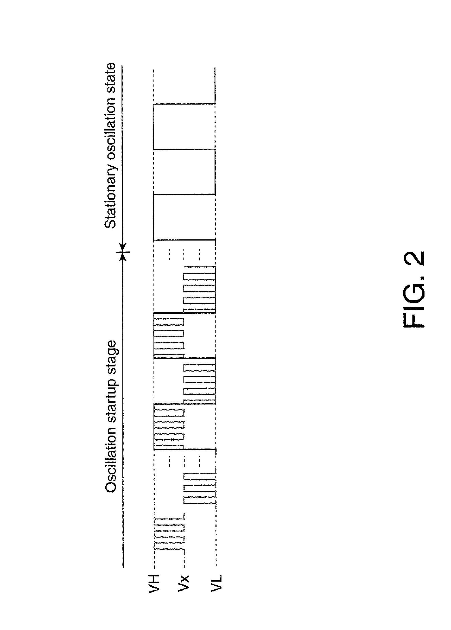
[0123]The oscillation drive device in accordance with the invention is not limited to the composition of Embodiment 1. An oscillation drive device in accordance with Embodiment 2 of the invention does not switch the output of the GCA 20 to the set voltage Vx in the oscillation startup stage, but instead, uses the output of the comparator 50 to perform oscillation startup in the oscillation startup stage, and also appropriately switches the output of the comparator 50 to the set voltage Vx to perform oscillation amplitude control by the GCA 20 in the stationary oscillation state.

[0124]2. Oscillation Drive Device

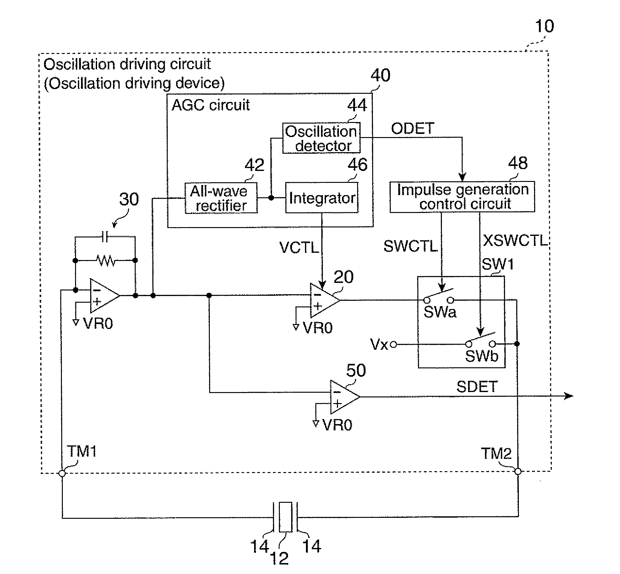
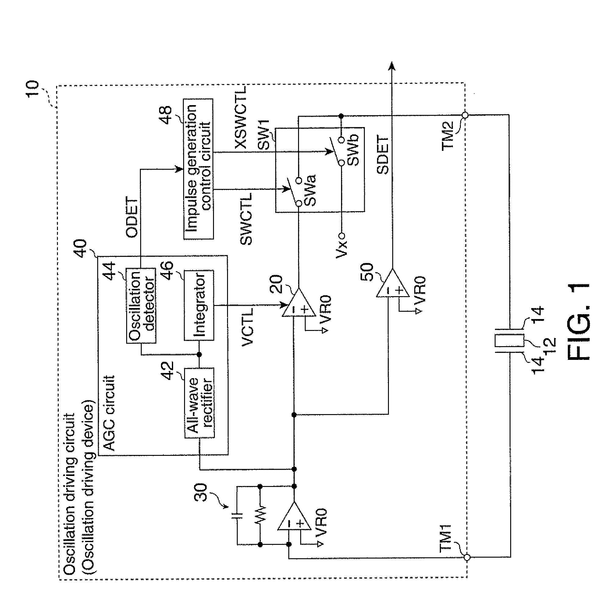
[0125]FIG. 8 is a block diagram of a composition example of the oscillation drive circuit, as an oscillation drive device in accordance with Embodiment 2 of the invention. Components of FIG. 8 that are the same as those of FIG. 1 will be appended with the same reference numbers, and their description may be omitted if appropriate.

[0126]An oscillation drive circuit 300 in accor...


PUM


Abstract

There is provided an oscillation drive device that forms an oscillation loop with a vibrator for exciting a driving vibration on the vibrator. The oscillation drive device includes: a comparator that excites a driving vibration on the vibrator based on a signal in the oscillation loop with a given voltage as a reference; an oscillation detector that detects oscillation in the oscillation loop; a signal generation circuit that generates a switching control signal based on an oscillation result given by the oscillation detector; and a switch circuit inserted between the vibrator in the oscillation loop and an output of the comparator, wherein, during an oscillation startup stage in which oscillation in the oscillation loop is not detected by the oscillation detector, the switch circuit alternately switches, based on the switching control signal, between a period in which the output of the comparator and the vibrator are electrically connected and a period in which a predetermined set voltage is supplied to the vibrator.

Description

[0001]The entire disclosure of Japanese Patent Application No. 2009-036250, filed Feb. 2, 2009 is expressly incorporated by reference herein.BACKGROUND[0002]1. Technical Field[0003]The present invention relates to oscillation drive devices, physical quantity measurement devices and electronic apparatuses.[0004]2. Related Art[0005]So-called gyroscopes are classified into various types including a rotation type and a vibration type depending on the method of detecting the force acting on an object. Above all, the vibration type gyroscopes are considered to be advantageous for size-reduction and cost-reduction from the viewpoint of their components. Among such vibration type gyroscopes, vibration type gyro-sensors that detect angular velocity acting on an object are known. The vibration type gyro-sensors include a piezoelectric vibration type gyro-sensor that excites a crystal element or a piezoelectric element that is reliable and advantageous in size-reduction. The piezoelectric vibr...

Claims


Application Information

Patent Timeline
Patent Type & Authority Applications(United States)
IPC IPC(8): G01C19/56H03L7/00G01C19/5614G01C19/5776
CPCG01C19/56H03B5/06H03K5/2481H03K5/1515H03B5/32
Inventor YOSHIDA, NAOKIKANAI, MASAHIRO
Owner SEIKO EPSON CORP
Why Eureka
Try Eureka