Dual clutch transmission

a transmission and clutch technology, applied in mechanical equipment, transportation and packaging, gearing, etc., can solve the problems of significant amount of installation space and significant limitations in installation options, and achieve the effect of less installation space, increased load and cost-effectiveness

Inactive Publication Date: 2010-08-19
ZF FRIEDRICHSHAFEN AG
View PDF10 Cites 6 Cited by
  • Summary
  • Abstract
  • Description
  • Claims
  • Application Information

AI Technical Summary

Benefits of technology

[0006]It is the task of this present invention, to propose a double clutch transmission as in the previously described genus, in which the power shiftable gear ratio steps are realized with the least spatial installation requirement, secondly, the transmission shall need only few parts, hereby keeping the manufacturing cost for the transmission low.
[0010]In the proposed double clutch transmission, in accordance with the invention, gear planes can be provided, as a so-called dual gear plane and / or single gear plane. In a dual gear plane, an idler gear wheel on the countershafts is each assigned to a fixed gear wheel of a transmission input shaft. To the contrary, in a single gear plane, just one idler gear wheel of a countershaft is assigned to a fixed gear wheel of a transmission input shaft. Due to the fact that in each dual gear plane one idler gear wheel can be used for at least two gears, the possible multi-use idler gear wheels enables the realization of a certain number of gear ratios with less gear planes. Hence, the physical length of the transmission can be reduced.
[0011]For the use of single gear planes, in which just one idler gear wheel of a countershaft is assigned to the fixed gear wheel of a transmission input shaft, a large range of transmission ratios is possible.
[0023]Independent from the particular embodiment of the double clutch transmission, the drive shaft and the output shaft, preferably, do not need to be positioned coaxially to each other, which realizes especially an installation space saving configuration. For instance, shafts, which are spatially positioned one after the other, can also be a slightly offset from each other. In that configuration, a direct gear with the transmission ratio of one can be realized via gear meshing, and can, in an advantageous way, be relatively freely shifted to the fifth, the sixth, or the seventh gear. Other configurations of the drive shaft and the output shaft are also possible.
[0025]Advantageously, the lower forward gears and the reverse gears can be activated through a starting, or shifting clutch, respectively, to hereby concentrate higher loads on this clutch and to construct the second clutch with less need for installation space and as more cost-effective. Especially, the gear planes in the proposed double clutch transmission can be positioned in a way that one can start, through the inner transmission input shaft or the outer transmission input shaft, hereby always a starting through the more appropriate clutch, which is also possible in a concentrically positioned, radially nested construction of the double clutch. Hereby and accordingly, the gear planes can be positioned as mirror-symmetric, or swapped, respectively. It is also possible the countershafts are swapped or positioned as in a mirror image.

Problems solved by technology

To achieve the desired gear ratio steps in this known double clutch transmission, a vast number of gear planes are required, so that a significant amount of installation space is needed.
Hence, the needed spatial installation requirement, in axial direction, increases with such transmission, so that the installation options are significantly limited with such known transmission.

Method used


Image

  • Dual clutch transmission
  • Dual clutch transmission
  • Dual clutch transmission

Examples


first embodiment

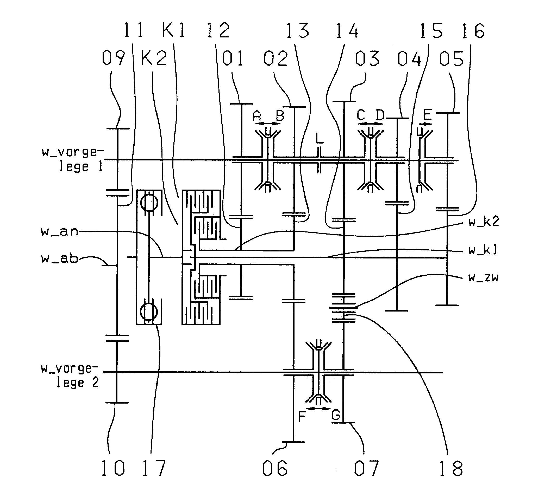
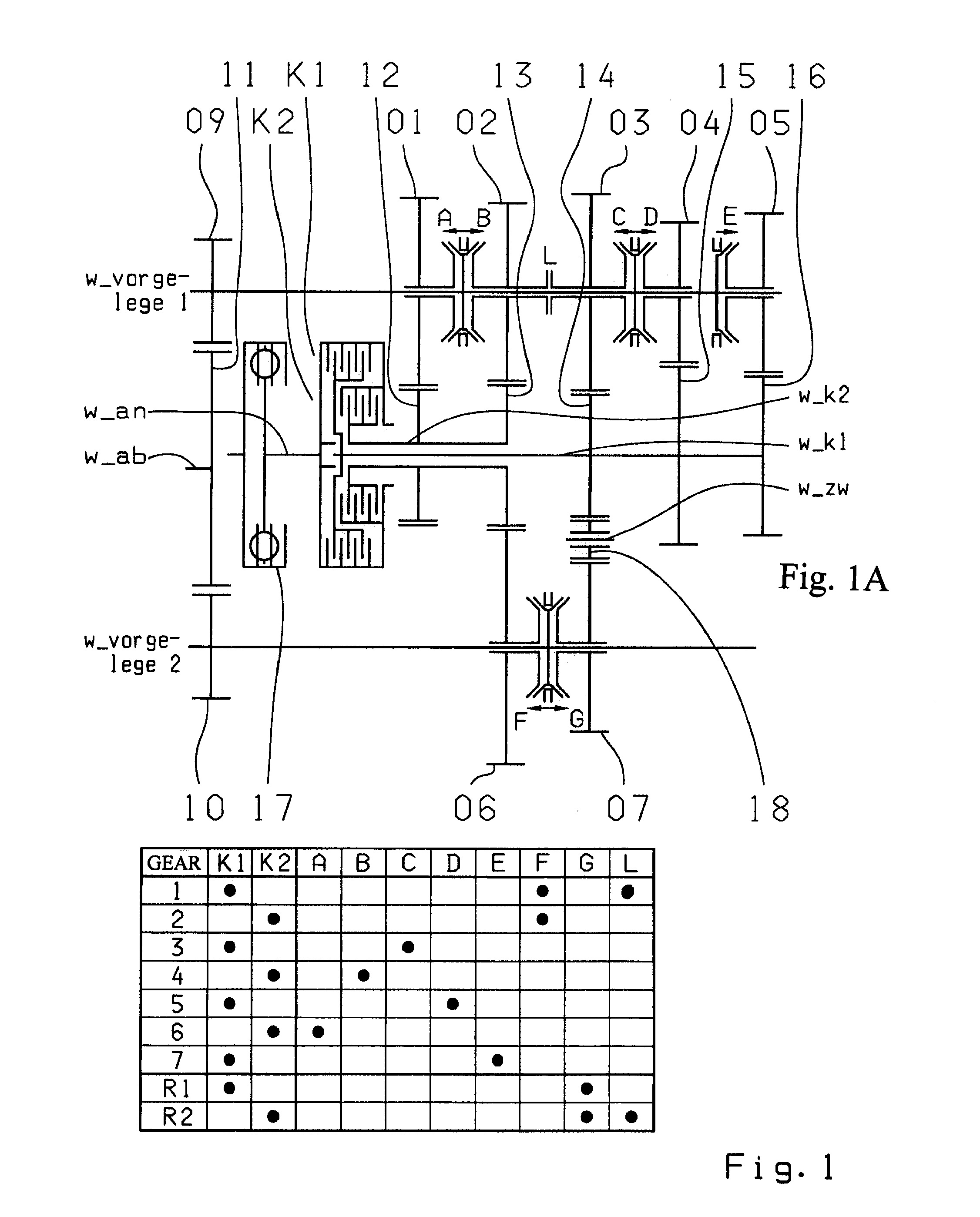
[0031]Five gear planes are provided for the inventive 7-gear double clutch transmission. In the first embodiment, in accordance with FIG. 1, the five gear planes 01-12, 02-06, 03-07, 04-15, 05-16 are realized through two fixed gear wheels 12, 13 on the second transmission input shaft w_K2 and through three fixed gear wheels 14, 15, 16 on the first transmission input shaft w_K1, which mesh with five idler gear wheels 01, 02, 03, 04, 05 on the first countershaft w_vorgelege1 and with two idler gear wheels 06, 07 on the second countershaft w_vorgelege 2.

[0032]In the embodiment , in accordance with FIG. 1, the second gear plane 02-06 and the third gear plane 03-07 are each designed as dual gear planes. In contrast, the first gear plane 03-12, the fourth gear plane 04-15, and the fifth gear plane 05-16 are each designed as single gear plane.

[0033]In the first gear plane 01-12, the fixed gear wheel 12 of the second transmission input shaft w_K2 meshes only with the idler gear wheel 01 on ...

second embodiment

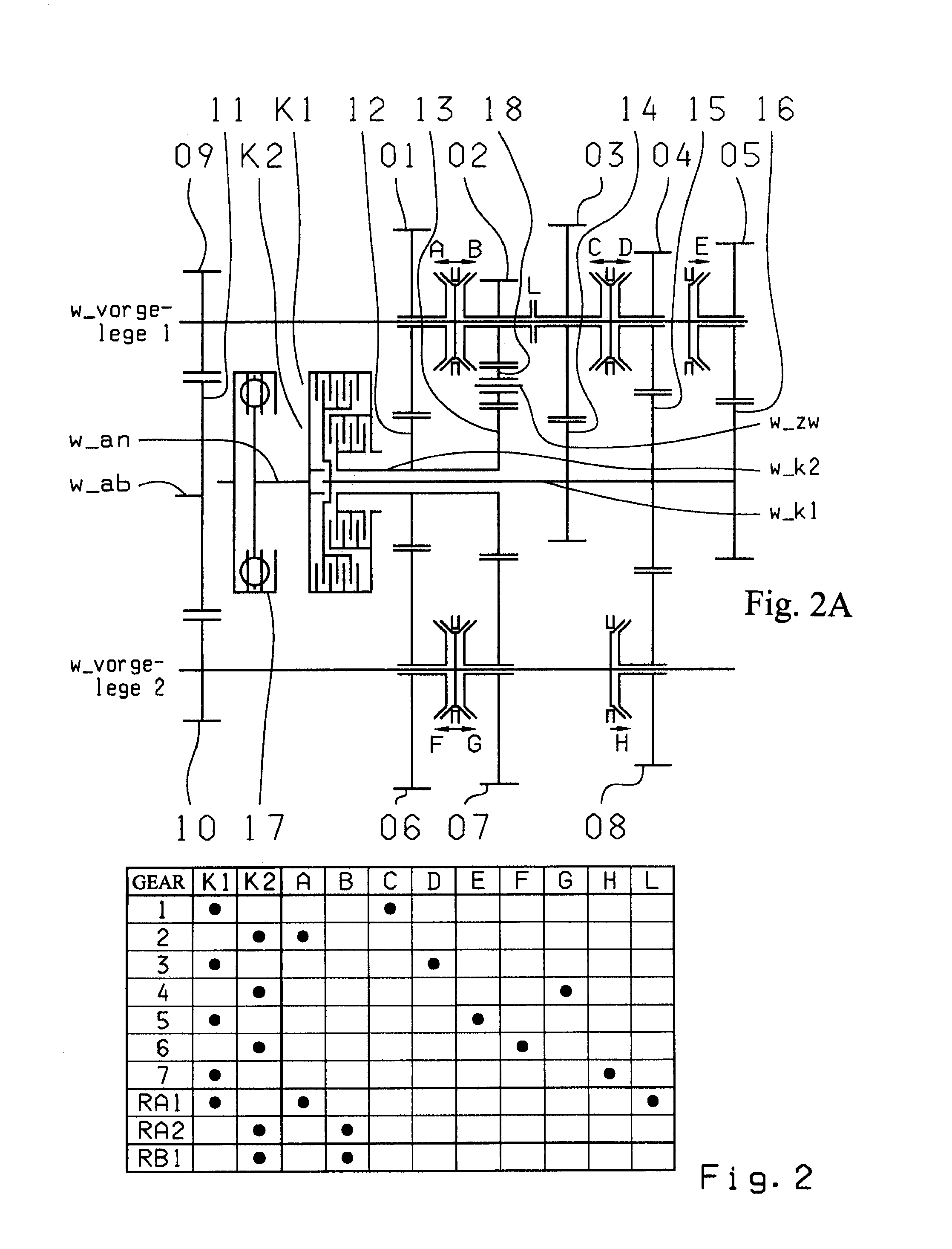
[0043]In the second embodiment, in accordance with FIG. 2, the five gear planes 01-06, 02-07, 03-14, 04-08, 05-16 are realized through two fixed gear wheels 12, 13 of the second transmission input shaft w_K2 and three fixed gear wheels 14, 15, 16, on the first transmission input shaft w_K1, which mesh with five idler gear wheels 01, 02, 03, 04, 05 on the first countershaft w_vorgelege 1 and three idler gear wheels 06, 07, 08 on the second countershaft w_vorgelege 2.

[0044]In accordance with the embodiment presented in FIG. 2, the first gear plane 01-06, the second gear plane 02-07, and the fourth gear plane 04-08, are each designed as dual gear planes. In contrary, the third gear plane 03-14 and the fifth gear plane 05-16 are designed as single gear planes.

[0045]The fixed gear wheel 12 of the second transmission input shaft w_K2 meshes in the first gear plane 01-06 with the idler gear wheel 01 of the first countershaft w_vorgelege 2, as well as with the idler gear wheel 06 of the sec...

third embodiment

[0057]In the third embodiment, in accordance with FIG. 3, the five gear planes 01-06, 02-07, 03-08, 04-15, 05-16 are realized through two fixed gear wheels 12, 13 on the second transmission input shaft w_K2 and three fixed gear wheels 14, 15, 16, on the first transmission input shaft w_K1, which mesh with five idler gear wheels 01, 02, 03, 04, 05 on the first countershaft w_vorgelege 1 and with three idler gear wheels 06, 07, 08 of the second countershaft w_vorgelege 2.

[0058]In the shown embodiment in accordance with FIG. 3, the first gear plane 01-06, the second gear plane 02-07, and the third gear plane 03-08 are designed as dual gear planes. In contrary, the fourth gear plane 04-15 and the fifth gear plane 05-16 are each designed as single gear planes.

[0059]In the first gear plane 01-06, the fixed gear wheel 12 on the second transmission input shaft w_K2 meshes with the idler gear wheel 01 of the first countershaft w_vorgelege 1, and the idler gear wheel 06 on the second counters...


PUM


Abstract

A double clutch transmission with two clutches connected to a drive shaft and to one of two transmission input shafts. Fixed gears are coupled to the input shafts and engage idler gears. Several coupling devices connect the idler gears to a countershaft which have an output gear that couple gears of an output shaft such that at least seven power shift forward gears and at least one reverse gear can be shifted, and four gear wheel planes are arranged in such a way that at least one power shift winding-path gear can be shifted via the shifting device, such that at least seven power shift forward gears and at least one reverse gear can be shifted, and five gear planes are positioned in such a way that at least one power shift winding-path gear can be shifted via a shifting device.

Description

[0001]This application is a National Stage completion of PCT / EP2008 / 063429 filed Oct. 8, 2008, which claims priority from German patent application serial no. 10 2007 049 269.5 filed Oct. 15, 2007.FIELD OF THE INVENTION[0002]The present invention relates to a double clutch transmission for a motor vehicle.BACKGROUND OF THE INVENTION[0003]Known from the publication DE 103 05 241 A1 is a 6-speed or 7-speed dual clutch transmission. The dual clutch transmission comprises two clutches, each connected with their inputs to the drive shaft and their output to one of the two transmission input shafts. The two transmission input shafts are coaxially arranged towards each other. In addition, two countershafts are positioned to be axially parallel to the transmission input shafts, their idler gear wheels mesh with the fixed gear wheels of the transmission input shafts. Furthermore, coupling devices that are axial movable, are supported on the countershaft and connected to shift the respective ...

Claims


Application Information

Patent Timeline
Patent Type & Authority Applications(United States)
IPC IPC(8): F16H3/16
CPCF16H3/006F16H3/093F16H2003/0807F16H2003/0826Y10T74/19233F16H2200/0056F16H2200/0086F16H2200/0091F16H2003/0931
Inventor RIEGER, WOLFGANG
Owner ZF FRIEDRICHSHAFEN AG
Why Eureka
Try Eureka