
Solar cell panel and method of fabricating solar cell panel

Inactive Publication Date: 2010-08-19
MITSUBISHI HEAVY IND LTD
View PDF2 Cites 8 Cited by
  • Summary
  • Abstract
  • Description
  • Claims
  • Application Information

AI Technical Summary

Benefits of technology

[0019]The present invention has been made under such circumstances, and an object of the present invention is to provide a solar cell panel that hardly retains any moisture and that has high reliability, and a method of fabricating the solar cell panel.
[0047]According to the present invention, moisture is prevented from remaining between the solar cell panel body and the frame. This improves reliability of the solar cell panel. In addition, automation of the process of attaching the frame to the solar cell panel body is possible. Furthermore, the number of processes in fabricating the solar cell panel is reduced, which simplifies the fabrication and enables the solar cell panel to be fabricated at lower cost.

Problems solved by technology

Accordingly, there is a possibility of problems such that moisture may remain in the “angular-U” portion of the approximately angular-U shaped cross-section; use of a gasket etc. may be necessary; the back sheet may be involved in the holding; and undulation or distortion of the solar cell panel body may have some influence.
Accordingly, there is a possibility of problems such that moisture may remain in the “angular-U” portion; and undulation or distortion of the solar cell panel body may have some influence.
Accordingly, there is a possibility of problems such that moisture may remain in the “angular-U” portion; the back sheet may be involved in the holding; and undulation or distortion of the solar cell panel body may have some influence.

Method used


Image

  • Solar cell panel and method of fabricating solar cell panel
  • Solar cell panel and method of fabricating solar cell panel
  • Solar cell panel and method of fabricating solar cell panel

Examples


Embodiment Construction

[0076]Embodiments of a solar cell panel and a method of fabricating the solar cell panel of the present invention will now be described with reference to the attached drawings.

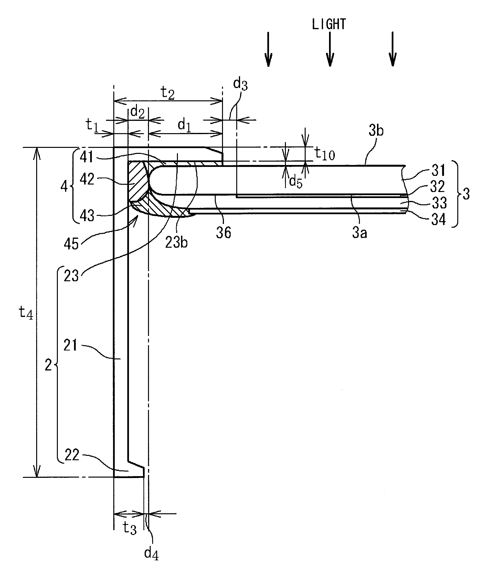
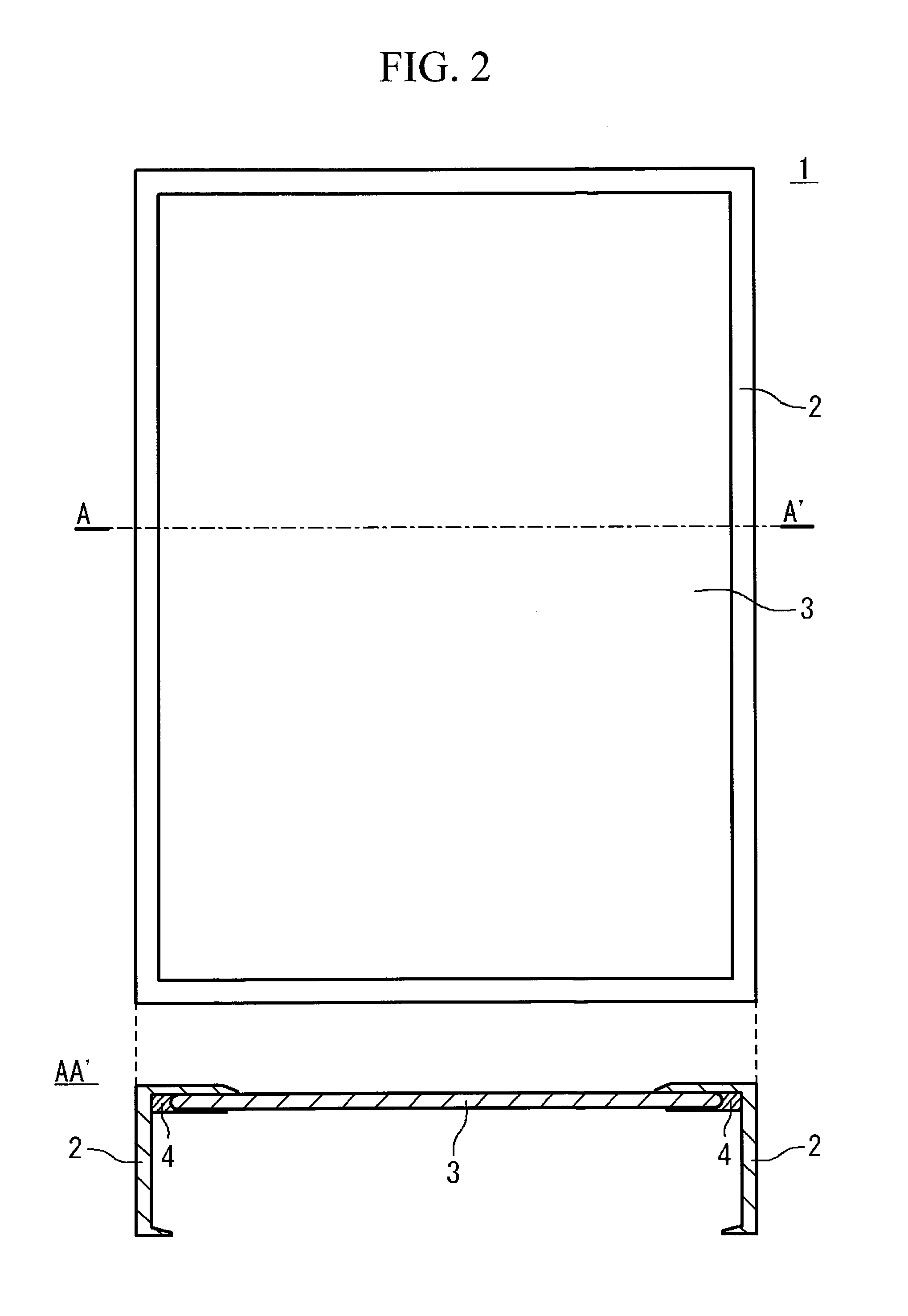
[0077]FIG. 2 contains a top view and a cross-sectional view illustrating a structure of the solar cell panel according to an embodiment of the present invention. The cross-sectional view shows the A-A′ cross-section of the top view. The solar cell panel 1 includes a frame 2, a solar cell panel body 3, and a joint 4. The cross-section of the solar cell panel 1 in the direction approximately perpendicular to the A-A′ cross-section is the same as that shown by the cross-sectional view of FIG. 2, except for the length of the solar cell panel body 3.

[0078]The solar cell panel body 3 includes a substrate and a plurality of solar cells mounted or formed on a first surface of the substrate. The plurality of solar cells are, for example, connected to each other in series. The solar cells are each composed of a transpar...


PUM

PropertyMeasurementUnit
Angleaaaaaaaaaa
Adhesion strengthaaaaaaaaaa
Distanceaaaaaaaaaa

Abstract

Provided is a solar cell panel that hardly retains any moisture between a solar cell panel body and a frame and enables automation of the process of attaching the frame to the solar cell panel body. The solar cell panel includes a solar cell panel body, a frame, and a joint. The solar cell panel body includes a substrate having a first surface on which photoelectric conversion elements are mounted. The frame has an approximately L-shaped cross-section. The joint bonds the frame and a second surface, opposite to the first surface, of the substrate.

Description

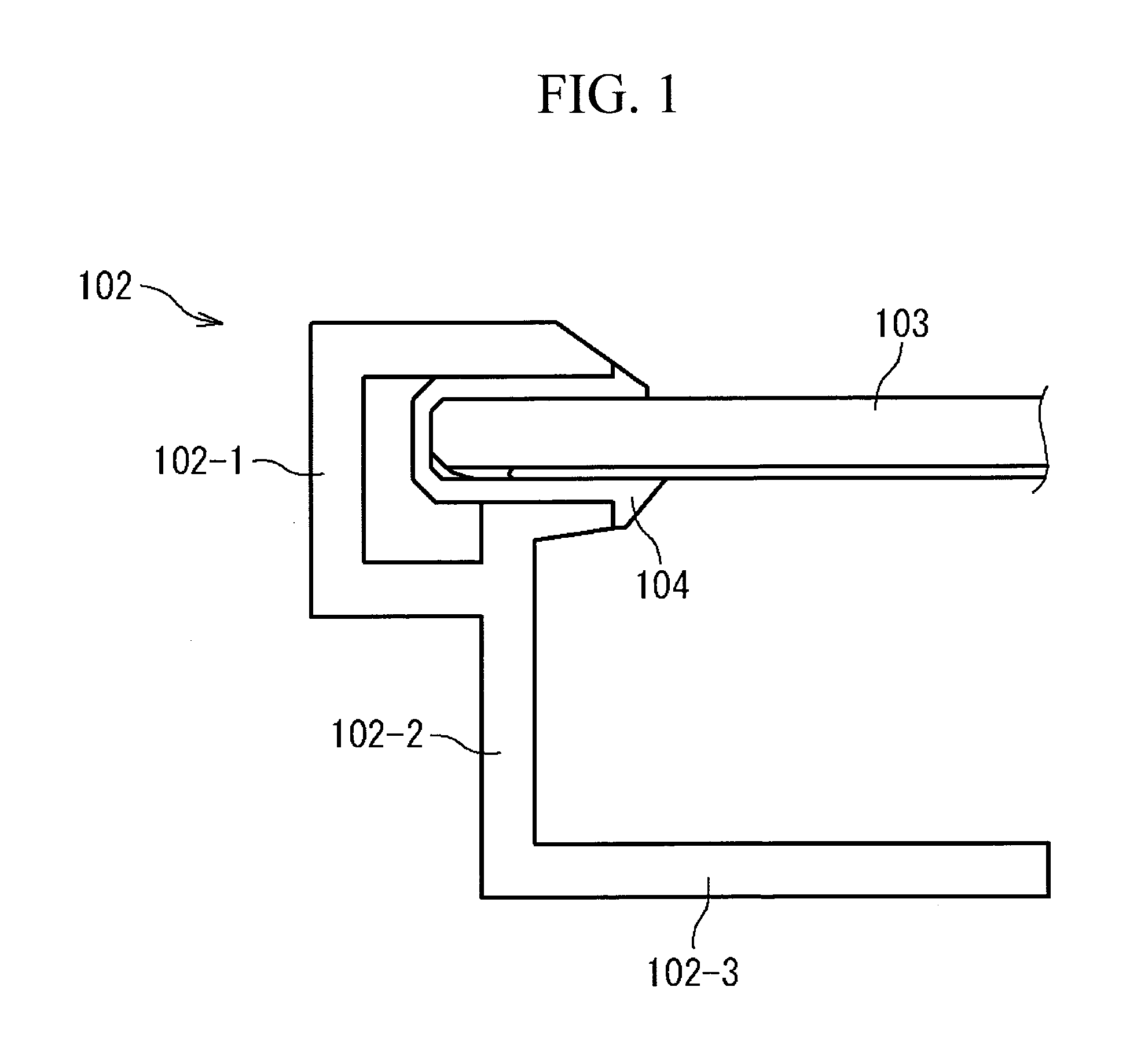
TECHNICAL FIELD[0001]The present invention relates to solar cells.BACKGROUND ART[0002]Known types of solar cells include thin-film solar cells where photoelectric conversion elements are disposed directly on, for example, a glass substrate and crystalline solar cells where photoelectric conversion elements are disposed on a crystal substrate. In the thin-film solar cells, for example, the surface having the photoelectric conversion elements is covered with a filler or a sealing agent to form a solar cell panel body. On the other hand, in the crystalline solar cells, for example, crystalline photoelectric conversion elements are bonded to the substrate, and the substrate is covered with a filler or a sealing agent to form a solar cell panel body. Such solar cell panel bodies are fixed to metal frames, such as aluminum frames, to form panel structures.[0003]FIG. 1 is a partial cross-sectional view showing an exemplary structure of a conventional solar cell panel. The solar cell panel ...

Claims


Application Information

Patent Timeline
IPC IPC(8): H01L31/048B29C65/52
CPCF24J2/464F24J2/465F24J2002/4676Y10T156/10Y02E10/50H02S20/00H01L31/18F24S80/40F24S80/70F24S2025/601H02S30/10
Inventor HORIOKA, TATSUJIMAMASE, SHINICHIRO
Owner MITSUBISHI HEAVY IND LTD
Learn More