
Power transmission system for use with downhole equipment

a transmission system and power transmission technology, applied in the direction of fluid removal, earth drilling and mining, borehole/well accessories, etc., can solve the problems of high current, limited cable length, and effective upper limit of 5-7 km

Active Publication Date: 2010-08-19
SCHLUMBERGER TECH BV
View PDF9 Cites 38 Cited by
  • Summary
  • Abstract
  • Description
  • Claims
  • Application Information

AI Technical Summary

Benefits of technology

[0005]In some embodiments, a power transmission system avoids some of the problems associated with existing AC systems and allows effective use of motors such as SRMs to drive downhole equipment such as ESPs. In some embodiments, a medium voltage DC power supply is provided to the downhole equipment.
[0014]For improved operational control, in some embodiments sensors are provided for monitoring one or more properties of the downhole equipment and a feedback system is provided for using the output of the sensors to control operation of the motor.
[0017]In some embodiments, operation of the system can include periodically reversing the direction of operation of the motor to clean the downhole equipment. Also, it may be desirable to operate the motor so as to operate the equipment at a very low speed when it is not in use. This can prevent blockage of pumps or the like and, with suitable sensors, or by monitoring the electrical load absorbed by the motor, can be used to determine the viscosity of fluids being pumped.
[0021]Using medium voltage DC avoids the need to use heavy, three-conductor cables to provide AC downhole. In some embodiments, the output voltage is lower than the medium voltage supplied from the surface.

Problems solved by technology

However, this can lead to certain limitations.
Because of the need to use three conductor cable, the overall weight of a long cable can be very high, leading to an effective upper limit on cable length of 5-7 km due to mechanical strength limitations.
The maximum operational voltage of such systems is limited to less than about 5 kV leading to the need to use high current if high power is required.
Because electrical power is typically provided in AC form and because most of the control of the power electronics is conducted at the surface, the start-up of ESPs is effectively uncontrolled and thus can potentially lead to burnout of motors if there is high physical resistance in the pump (e.g. due to viscous oils, build-up of deposits, etc.).

Method used


Image

  • Power transmission system for use with downhole equipment
  • Power transmission system for use with downhole equipment
  • Power transmission system for use with downhole equipment

Examples


Embodiment Construction

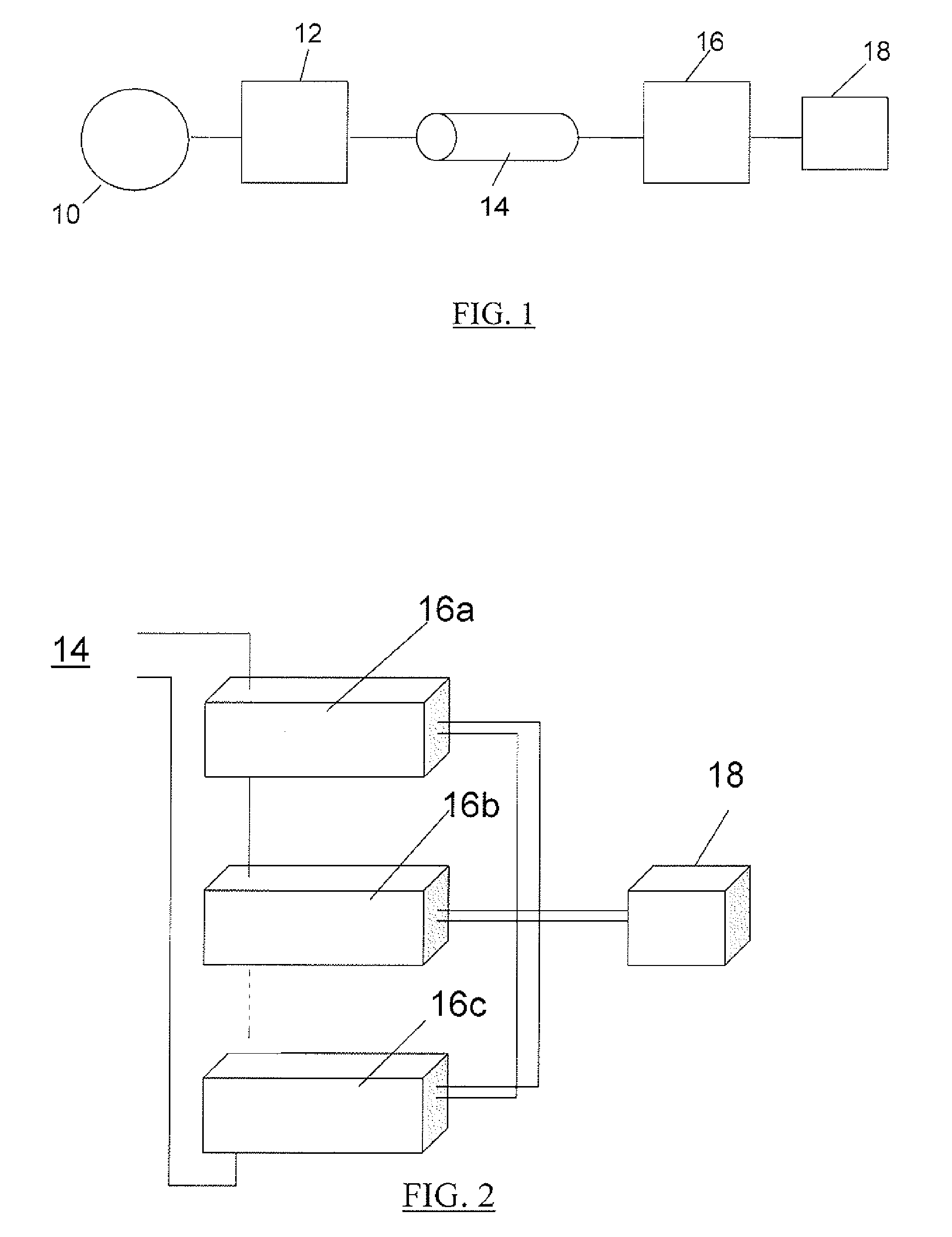
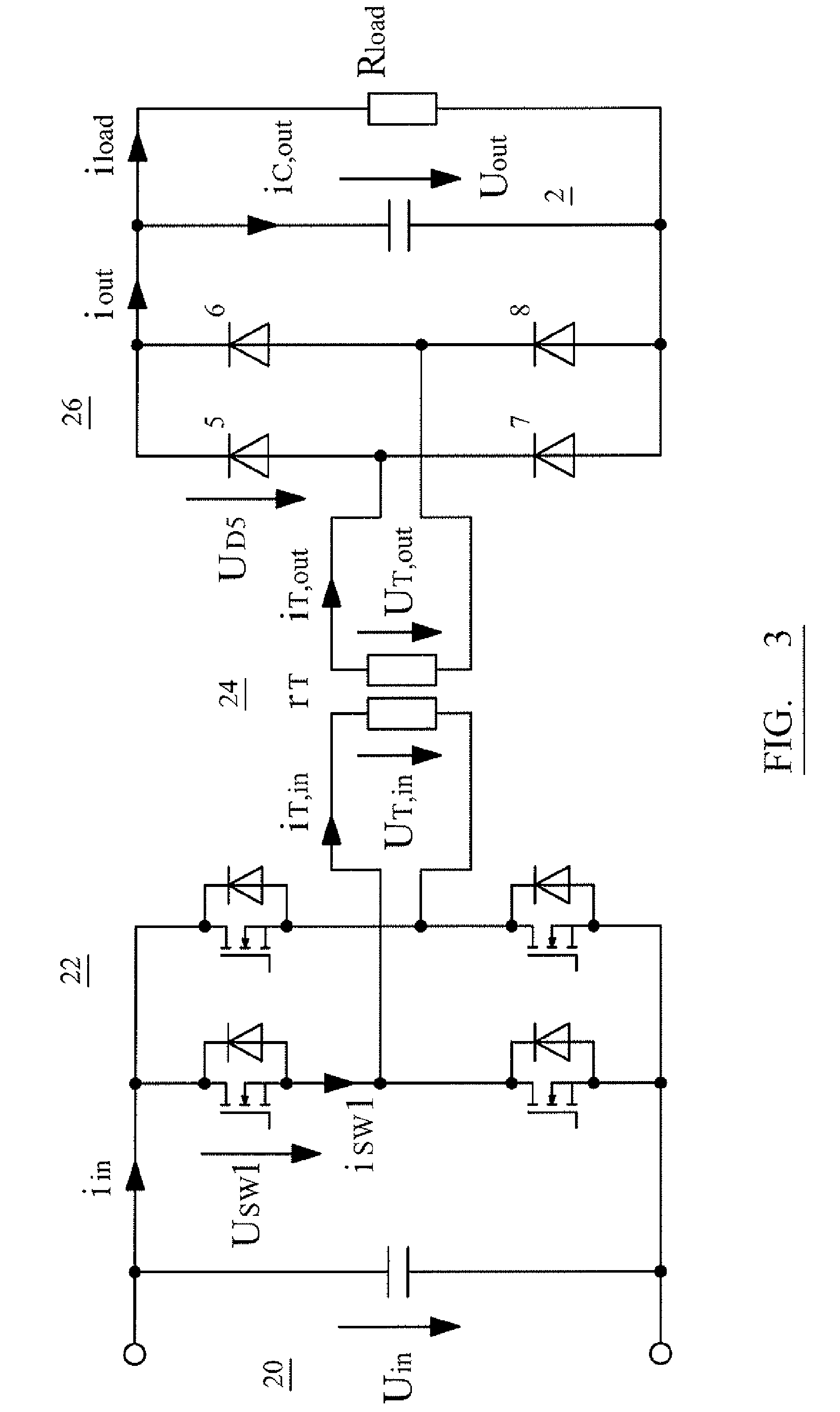
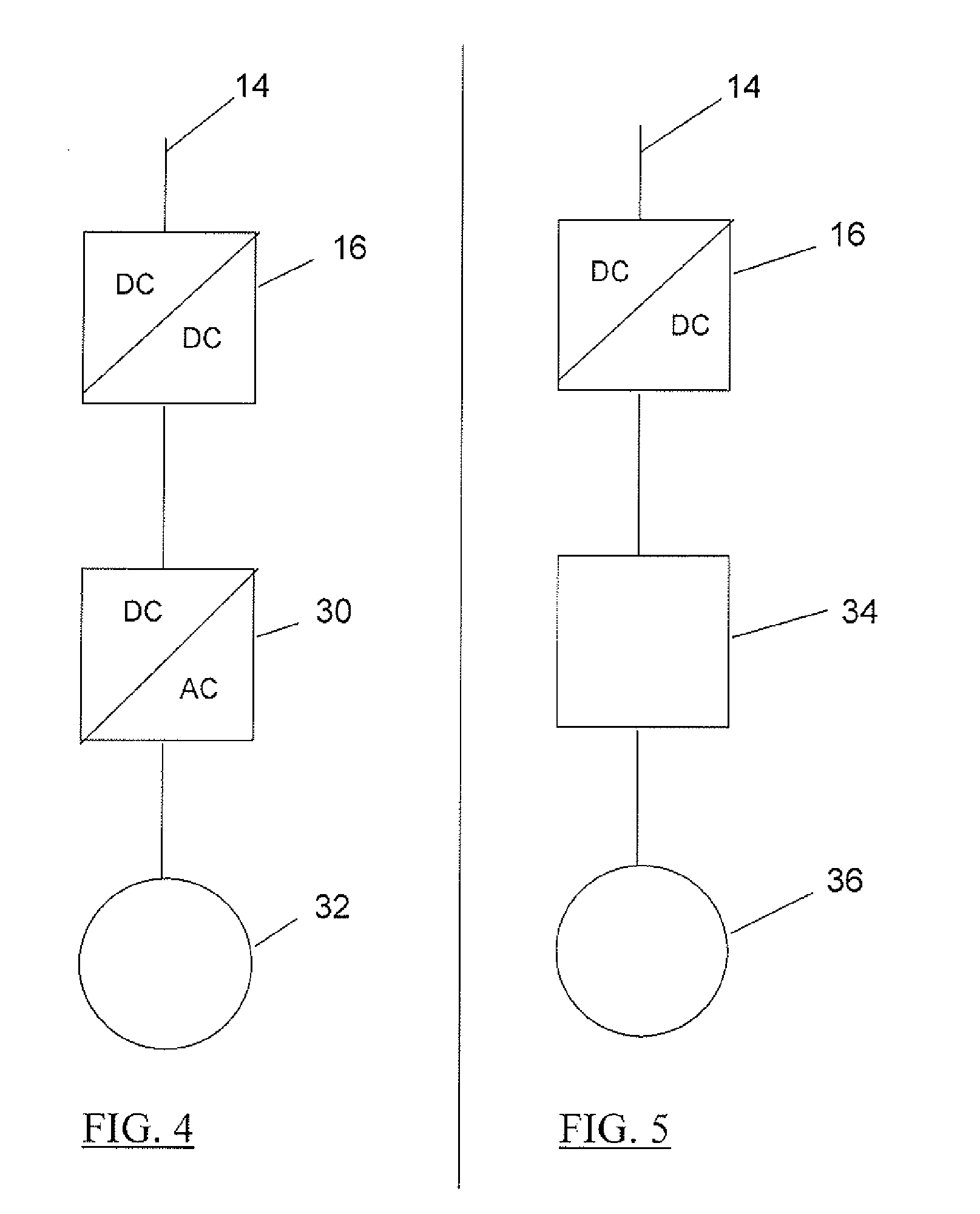
[0034]FIG. 1 shows schematically how an embodiment of a transmission system is configured. A three-phase power source 10 is provided at the surface of the borehole (not shown). In some embodiments, the three-phase power source 10 may provide a low voltage AC supply of around 400V at 50 Hz. An AC / DC converter 12 is used to turn this into a medium voltage DC transmission supply of 10 kV. This can be passed downhole by means of a single-phase, two-conductor cable 14. The relatively high transmission voltage (10 kV) means that a correspondingly lower current can be used to meet downhole power requirements, which in turn leads to lower power losses along the cable. Thus a relatively light, thin cable can be used for the transmission, avoiding some of the physical limitations of a three-phase AC system.

[0035]A DC / DC converter 16 is located downhole at the end of the cable 14. The purpose of this converter is to convert the medium voltage DC supply of 10 kV on the cable to a level usable b...


PUM


Abstract

A power transmission system for use with downhole equipment in a borehole includes a power source that is positioned at the surface providing a DC power supply, a downhole DC / DC converter and a two-conductor cable connecting the power source and the downhole DC / DC converter. The power transmission system receives the DC voltage supply as an input and provides an output DC supply at a different voltage to the DC power supply for provision to the downhole equipment.

Description

TECHNICAL FIELD[0001]This invention relates to power transmission system for use with downhole equipment. In particular, the invention relates to a system permitting the use of switched reluctance motors (SRMs) for driving electric submersible pumps (ESPs)BACKGROUND ART[0002]In oil well applications, there are a number of devices that operate downhole using electric power. Power is typically provided as three-phase AC current. However, this can lead to certain limitations. Because of the need to use three conductor cable, the overall weight of a long cable can be very high, leading to an effective upper limit on cable length of 5-7 km due to mechanical strength limitations. The maximum operational voltage of such systems is limited to less than about 5 kV leading to the need to use high current if high power is required.[0003]ESPs are well-known for pumping oil from boreholes. They are positioned at downhole locations and are provided with electric power from the surface via a cable...

Claims


Application Information

Patent Timeline
Patent Type & Authority Applications(United States)
IPC IPC(8): E21B4/04E21B43/00
CPCE21B4/04H02J1/06E21B43/128E21B41/0085
Inventor NEUHAUS, CHRISTOPHKOENIG, ANDREASDE DONCKER, RIK
Owner SCHLUMBERGER TECH BV
Learn More