Position indicator, circuit component and input device

a technology of position indicators and circuit components, applied in the direction of instruments, magnetic measurements, measurement devices, etc., can solve the problem of difficult to reduce the outer diameter of the position indicators

Active Publication Date: 2010-08-19
WACOM CO LTD
View PDF2 Cites 57 Cited by
  • Summary
  • Abstract
  • Description
  • Claims
  • Application Information

AI Technical Summary

Benefits of technology

[0020]According to the present invention, it is possible to detect the rotation (roll) of the position indicator with respect to the axial direction of the position indicator and to also detect the pen pressure with a bar-like rod.

Problems solved by technology

Thus, it was difficult to reduce the outer diameter of the position indicator.

Method used


Image

  • Position indicator, circuit component and input device
  • Position indicator, circuit component and input device
  • Position indicator, circuit component and input device

Examples


Embodiment Construction

)

[0035]A position indicator and an input device according to a first embodiment of the present invention will be described below with reference to FIGS. 1 to 14B. Note that, in the drawings, like components are denoted by like numerals.

[0036]Description will be given in the following order:

[0037]1. Configuration of the First Embodiment

[0038]2. Operation of the First Embodiment

[0039]3. Modifications

1. Configuration of the First Embodiment

Input Device

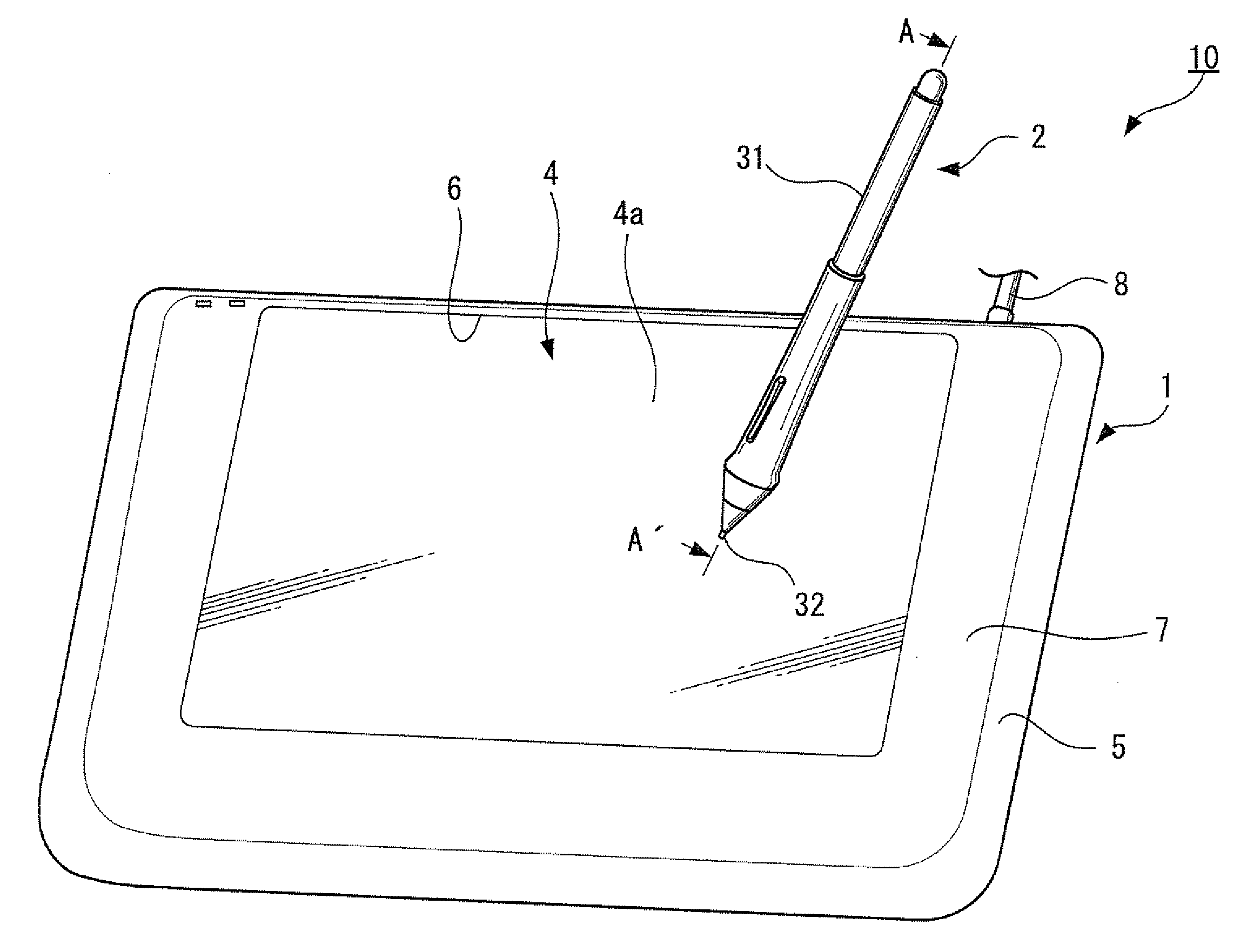
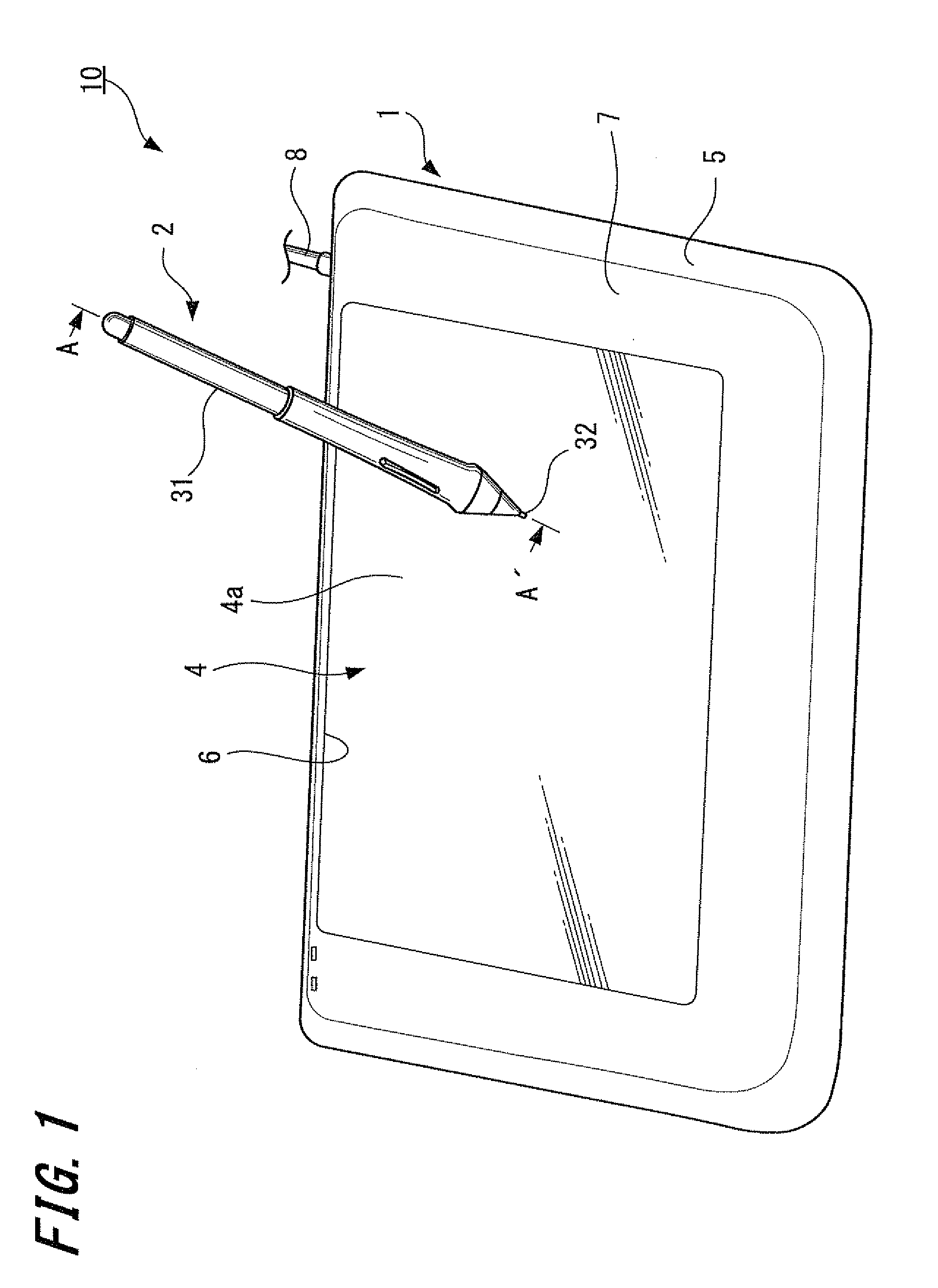
[0040]First, a brief description of an input device 10 according to a first embodiment of the present invention will be set forth below with reference to FIG. 1.

[0041]The input device 10 according to the present embodiment includes a position detecting device 1 and a position indicator 2 that inputs information to the position detecting device 1. The position indicator 2 indicates its own position on the position detecting device 1 based on the electromagnetic resonance technology.

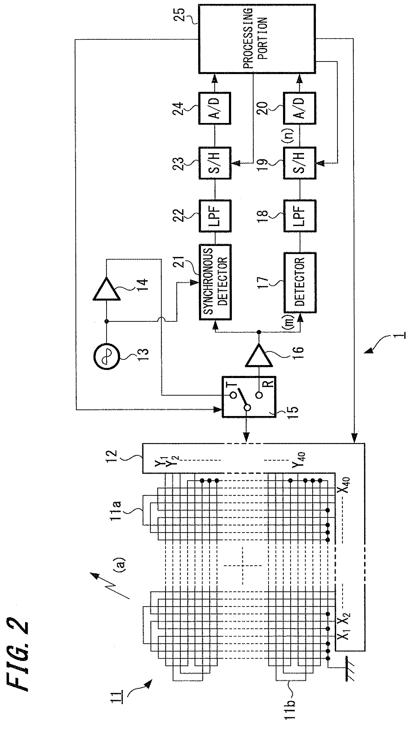
[0042][Position Detecting Device]

[0043]The configuration o...


PUM


Abstract

A position indicator includes a tubular core member, a first coil, a second coil, a substantially bar-like rod, a pen-pressure detecting element, at least one capacitor, and a switch. The tubular core member is formed by a substantially bar-like first magnetic core and a substantially bar-like second magnetic core, which are combined in a transversal direction thereof to form a through-hole therebetween. At least one of the first and second magnetic cores may include a recessed portion formed therein extending in the axial direction thereof. The first coil is wound around the tubular core member, and the second coil is wound around the second magnetic core. The rod is inserted into the through-hole of the tubular core member. The pen-pressure detecting element detects a pressure applied to an end of the rod (i.e., the pen tip). The capacitor is connected to the first coil to form a resonant circuit. The switch controls “on” and “off” states of the second coil for the purpose of calculating a rotation angle of the position indicator about its axis.

Description

CROSS REFERENCES TO RELATED APPLICATIONS[0001]The present invention claims priority under 35 U.S.C. §119 from Japanese Patent Application JP 2009-033978 filed in the Japanese Patent Office on Feb. 17, 2009, the entire contents of which being incorporated herein by reference.BACKGROUND OF THE INVENTION[0002]1. Field of the Invention[0003]The present invention relates to a position indicator whose rotation angle with respect to an axial direction can be detected, a circuit component used in the position indicator, and an input device having the position indicator.[0004]2. Description of the Related Art[0005]In recent years, input devices which operate based on electromagnetic resonance technology have been used as input devices for a personal computer and the like. Such input devices generally comprise a pen-like position indicator and a position detecting device having an input surface, on which an input operation is performed using the position indicator. An input operation using th...

Claims


Application Information

Patent Timeline
Patent Type & Authority Applications(United States)
IPC IPC(8): G01B7/14
CPCG06F3/03545G01D5/241G06F3/047G06F3/038
Inventor KATSURAHIRA, YUJIFUJITSUKA, HIROYUKIHOSAKA, KIMIYOSHI
Owner WACOM CO LTD
Why Eureka
Try Eureka