Mobile RFID reader and RFID communication method using shared system clock

Inactive Publication Date: 2010-08-19
ELECTRONICS & TELECOMM RES INST
View PDF6 Cites 10 Cited by
  • Summary
  • Abstract
  • Description
  • Claims
  • Application Information

AI Technical Summary

Benefits of technology

[0010]According to the present invention, clock for synchronizing the mobile RFID readers can be shared without changing hardware of the conventional RFID device. Also, uplink communication for synch

Problems solved by technology

However, in mobile radio frequency identification (RFID) reader technology, the RFID readers do not have a means of sharing timing information and thus, cannot synchronize with a centralized system clock.
In addition, even though any RFID readers exist in a same management area and distributed devices are connected to each other in a wire or by a central adjusting device, when other

Method used


Image

  • Mobile RFID reader and RFID communication method using shared system clock
  • Mobile RFID reader and RFID communication method using shared system clock
  • Mobile RFID reader and RFID communication method using shared system clock

Examples


Example

BEST MODE

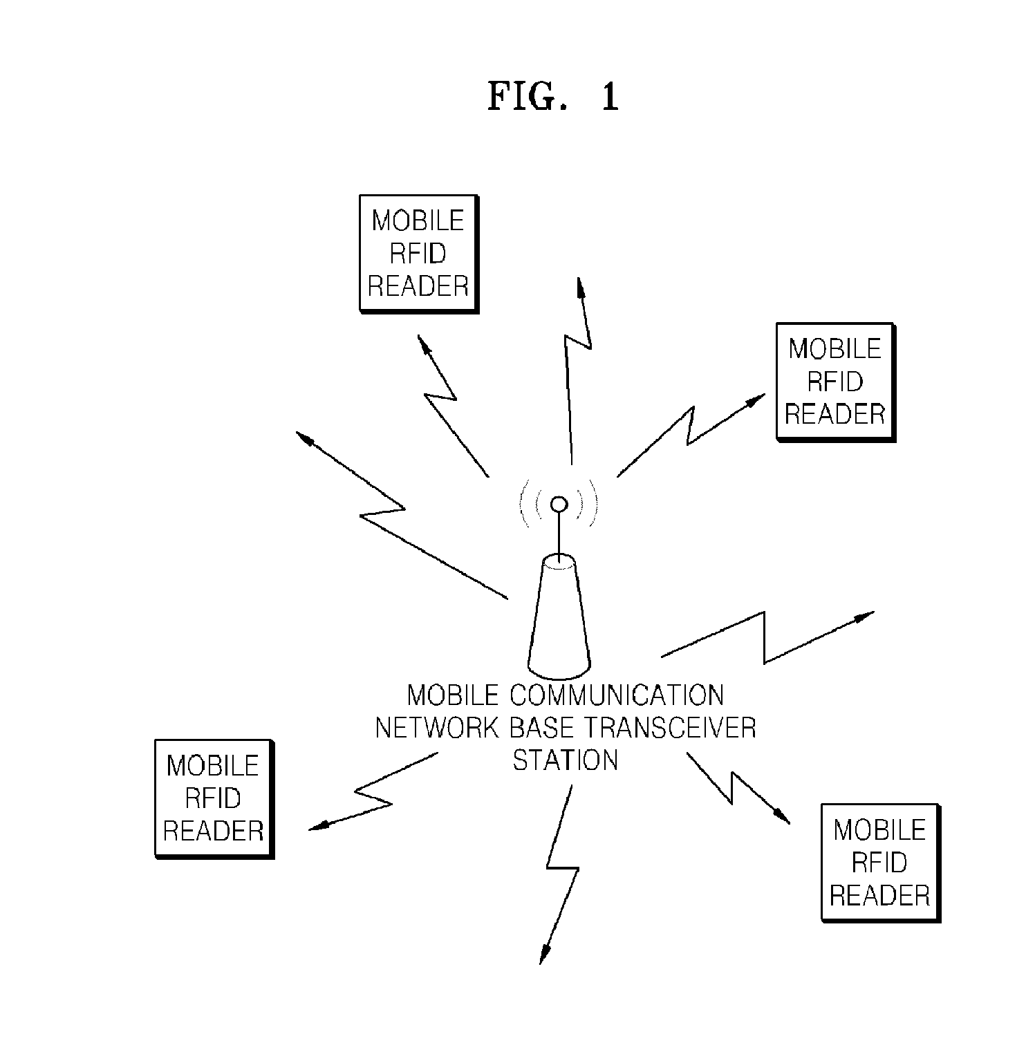
[0020]According to an aspect of the present invention, there is provided a mobile radio frequency identification (RFID) reader including: a mobile communication unit generating a clock synchronization signal at a specific pattern of a downlink frame that is broadcasted from a base transceiver station; and a RFID reader unit sharing a system clock with other mobile RFID readers after the system clock is synchronized by the clock synchronization signal.

[0021]The mobile RFID reader may further include an interface unit transmitting the clock synchronization signal to the RFID reader unit from the mobile communication unit.

[0022]The specific pattern of the frame may include information indicating starting of the downlink frame or starting of specific burst forming the frame. The burst may include a normal burst, a synchronization burst, an access burst, a frequency correction bursts, and a dummy bursts.

[0023]The RFID reader unit may generate a time slot for RFID communication w...


PUM


Abstract

The present invention relates to a mobile radio frequency identification (RFID) reader and a RFID communication method using a shared system clock. According to the present invention, clock for synchronizing the mobile RFID readers can be shared without changing hardware of a conventional RHD device. Also, since the shared clock is used, a technology for preventing a collision with the readers can be easily realized in a mobile multi-reader environment.

Description

TECHNICAL FIELD[0001]The present invention relates to a mobile radio frequency identification (RFID) reader, a RFID communication system, and a RFID communication method using a shared system clock, and more particularly, to a mobile RFID reader and a RFID communication method capable of providing accurate timing information so as to be used in a technology for preventing a collision with each different readers.[0002]The present invention is supported by the Information Technology (IT) Research & Development (R&D) program of the Ministry of Information and Communication (MIC) and the Institute for Information Technology Advancement (IITA) [2006-S-023-02, Development of advanced RFID system technology].[0003]This application claims the benefit of Korean Patent Application Nos. 10-2007-0103150, filed on Oct. 12, 2007, 10-2008-0078120, filed on Aug. 8, 2008, in the Korean Intellectual Property Office, the disclosure of which is incorporated herein in its entirety by reference.BACKGROUN...

Claims


Application Information

Patent Timeline
IPC IPC(8): G06K17/00
CPCG06K7/0008G06K7/10297H04W56/0085H04J3/0644G06K7/10356G06K17/00H04B5/00H04B5/02
Inventor PARK, CHAN-WONSEONG, NAK-SEONPREISHUBER-PFLUEGL, JOSEFTSCHISCHE, DAVIDCHOI, GIL-YOUNGPYO, CHEOL-SIGCHAE, JONG-SUK
Owner ELECTRONICS & TELECOMM RES INST
Why Eureka
Try Eureka