Distance measuring device

Inactive Publication Date: 2010-08-19
RCS +1
View PDF5 Cites 60 Cited by
  • Summary
  • Abstract
  • Description
  • Claims
  • Application Information

AI Technical Summary

Benefits of technology

[0030]Conventional accurate distance measurement systems include a radar or transponder that measures the distance from a target by measuring the time taken for an ultrasonic signal, radio frequency signal or optical signal transmitted from a single signal transmitting means to be reflected or retransmitted from the target and received by a single signal receiving means and a “VLF radio position location system” that has a single signal transmitting means that transmits a FSK-modulated radio frequency signal and a single signal receiving means that receives the signal and measures the distance by detecting the delay time between the carrier signal and the FSK-modulated signal. However, these systems have problems that the systems are expensive, the distance measurement accuracy is low particularly for relat

Problems solved by technology

The conventional technique shown in FIG. 11 has a problem that it is difficult to achieve high accuracy in relatively short distance measurement within a range of 300 m without modification, although it can achieve approximate long distance measurement, because it is difficult for the receiver to detect the time of change of the frequency of the VLF signal between f0 and f0+50 Hz without error.
However, it is difficult to detect the transmission start point 0 from the two distance measuring signals transmitted from a single fixed station with high accuracy.
Thus, there is a problem

Method used


Image

  • Distance measuring device
  • Distance measuring device
  • Distance measuring device

Examples


embodiment 1

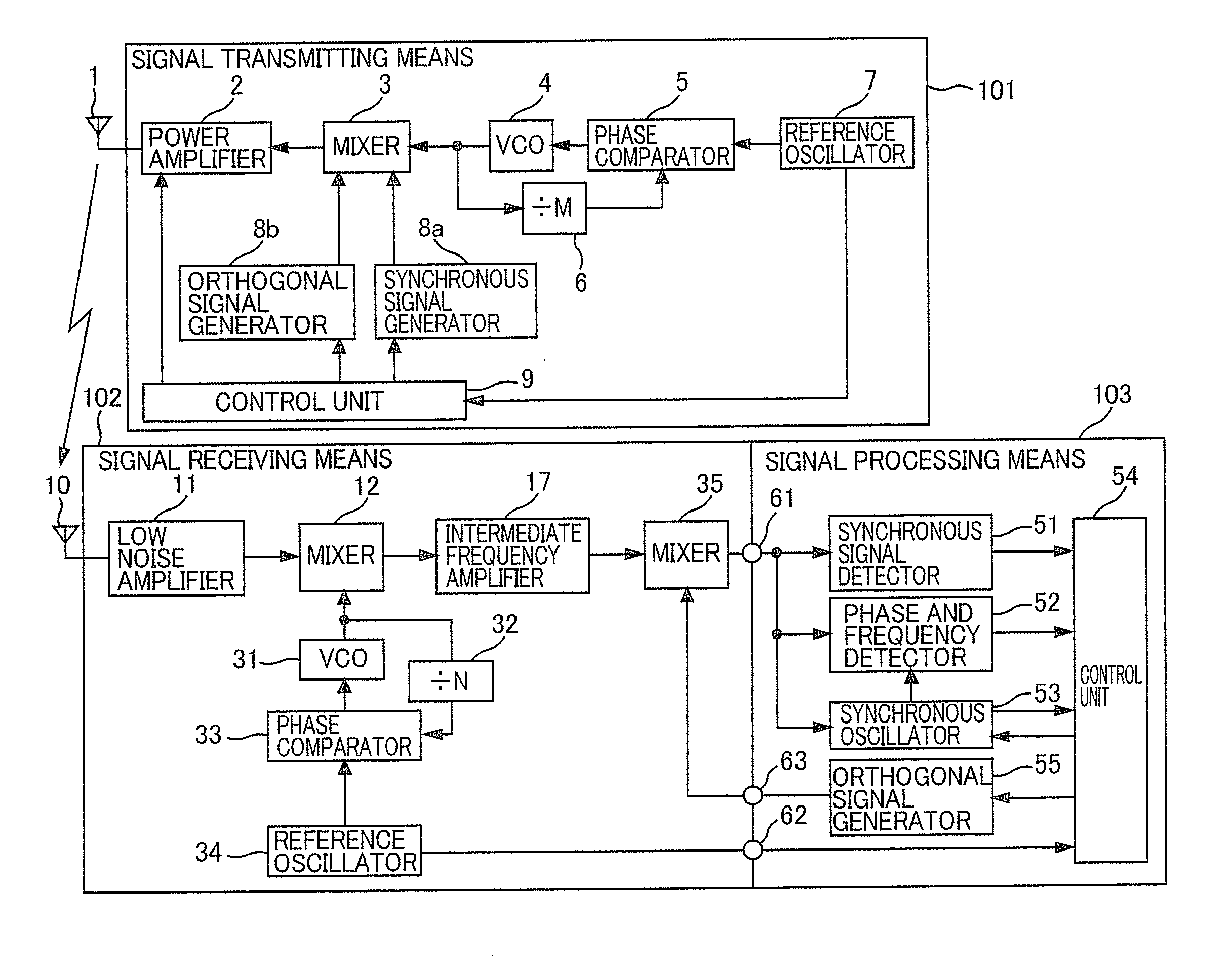
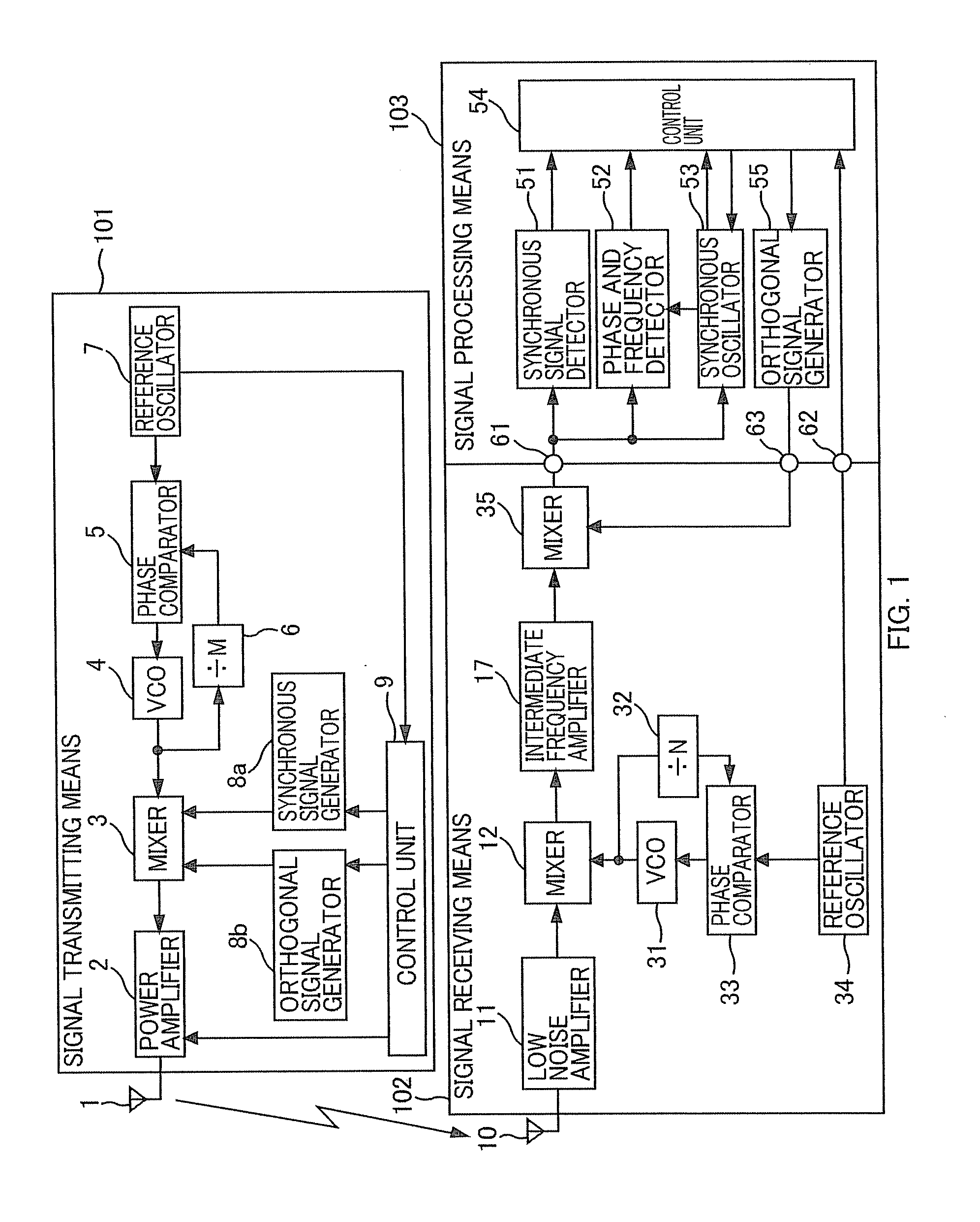
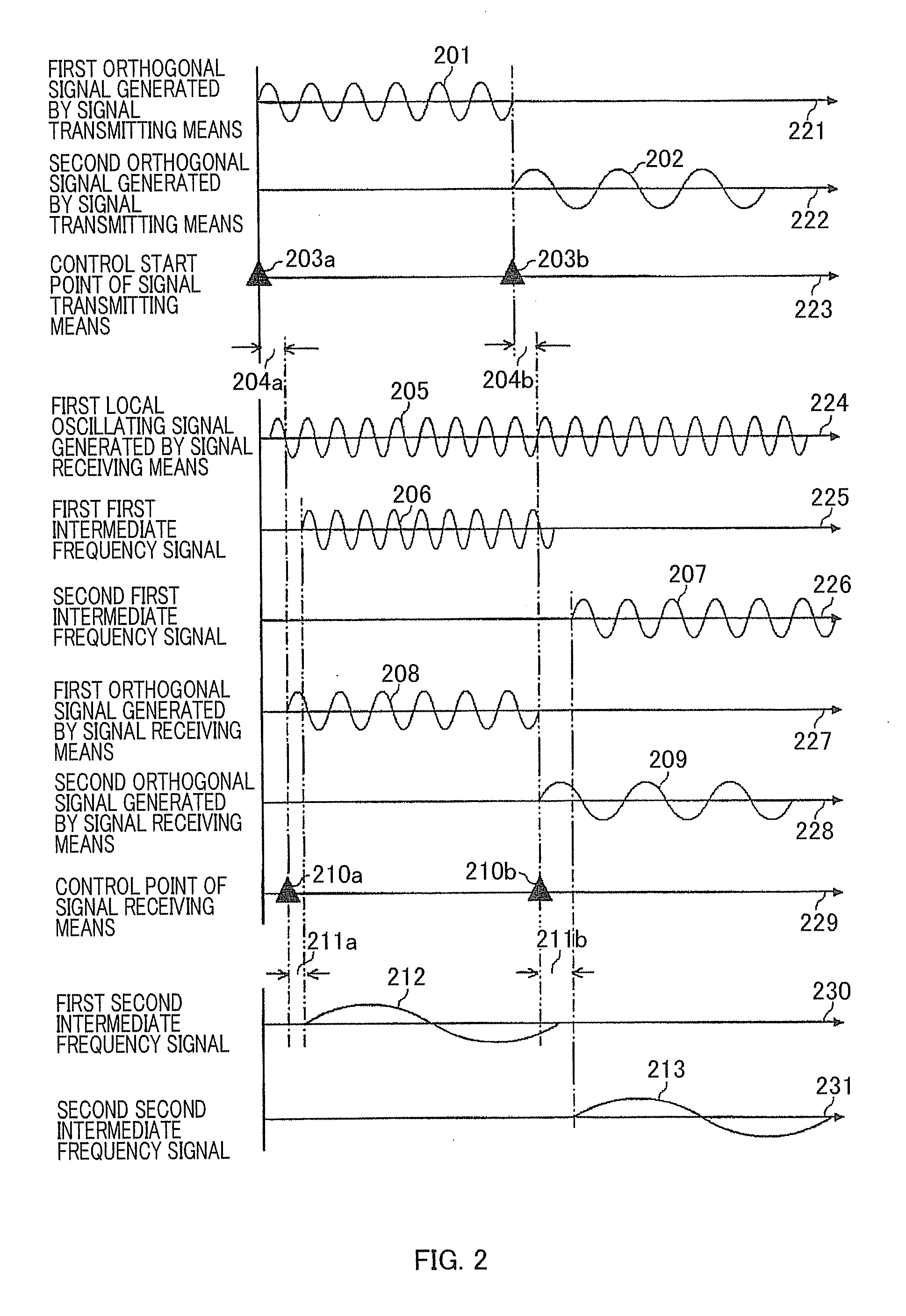
[0044]FIG. 1 is a block diagram showing a distance measuring device according to a first embodiment of the present invention, and FIG. 2 is a diagram showing exemplary flows of signals. In FIG. 1, reference numeral 101 denotes a signal transmitting means, reference numeral 1 denotes an antenna, reference numeral 2 denotes a power amplifier, reference numeral 3 denotes a mixer, reference numeral 4 denotes a voltage-controlled oscillator, reference numeral 5 denotes a phase comparator, reference numeral 6 denotes a frequency divider, reference numeral 7 denotes a reference oscillator, reference numeral 8a denotes a synchronous signal generator, reference numeral 8b denotes an orthogonal signal generator, and reference numeral 9 denotes a control unit. Furthermore, reference numeral 102 denotes a signal receiving means, reference numeral 10 denotes an antenna, reference numeral 11 denotes a low noise amplifier, reference numeral 16 denotes a first mixer, reference numeral 17 denotes a ...

embodiment 3

[0072]FIG. 3 is a diagram showing a distance measuring device according to an embodiment 2 of the present invention. In FIG. 3, reference numeral 102 denotes a signal receiving means, reference numeral 10 denotes an antenna, reference numeral 11 denotes a low noise amplifier, reference numeral 16 denotes a mixer, reference numeral 17 denotes an intermediate frequency amplifier, reference numeral 31 denotes a voltage-controlled oscillator, reference numeral 32 denotes a frequency divider, reference numeral 33 denotes a phase comparator, reference numeral 35 denotes a reference oscillator, reference numeral 103 denotes a signal processing means, reference numeral 51 denotes a synchronous signal detector, reference numeral 52 denotes a phase and frequency detector, reference numeral 53 denotes a synchronous oscillator, reference numeral 54 denotes a control unit, reference numeral 56 denotes a frequency multiplier / divider, and reference numerals 61 and 62 denote connection points.

[0073...

embodiment 4

[0129]FIG. 9 is a diagram showing a configuration of a distance measuring device according to a fourth embodiment of the present invention. In FIG. 9, reference numerals 1a and 1b denote a plurality of antennas connected to a signal transmitting means 101, reference numeral 1c denotes an antenna switching means for switching between the plurality of antennas 1a and 1b, reference numerals 10a and 10b denote a plurality of antennas connected to a signal receiving means 102, reference numeral 10c denotes an antenna switching means for switching between the plurality of antennas 10a and 10b, and reference numeral 66 denotes a connection point between the control unit 54 and the antenna switching means 10c. The remaining components are the same as those shown in FIG. 1.

[0130]The plurality of antennas 1a, 1b and / or the plurality of antennas 10a, 10b are disposed at intervals equal to or smaller than the wavelength of the carrier signal or sub-carrier signal of the radio frequency signal a...


PUM


Abstract

Problems The present invention relates to a distance measuring device that measures the distance between a single signal transmitting means and a single signal receiving means with high accuracy by the signal transmitting means transmitting radio frequency signals.
Means for Solving the Problems A distance measuring device is comprised of a signal transmitting means (101), a signal receiving means (102) and a signal processing means (103). The signal transmitting means transmits radio frequency signals, the components of which are a plurality of measuring signals in synchronization with an output reference signal of a reference oscillator (7). The signal receiving means (102) generates a first local oscillating signal in synchronization with an output reference signal of a reference oscillator (34), mixes the first local oscillating signal with a received signal, converts the mixed signal to first intermediate signals with at least a plurality of different frequencies, mixes the first intermediate signals corresponding to the measuring signals with a plurality of second local oscillating signals with at least different frequencies in synchronization with or orthogonal to an output signal of a second mixer (35), and converts the mixed signal to a plurality of second intermediate signals. The signal processing means (103) detects a phase difference of the second intermediate signals and measures the distance between the signal transmitting means (101) and the signal receiving means (102) with high accuracy.

Description

TECHNICAL FIELD[0001]The present invention relates to a distance measuring device that measures the distance between a single signal transmitting means and a single signal receiving means with high accuracy by the signal transmitting, means transmitting a plurality of ultrasonic signals, radio frequency signals or optical signals that differ at least in frequency and the signal receiving means receiving the signals.BACKGROUND ART[0002]Distance measuring systems based on a plurality of radio signals at different frequencies have already been proposed (see the Patent Documents 1 to 5, for example).[0003]Patent Document 1: U.S. Pat. No. 4,087,816[0004]Patent Document 2: Japanese Patent Laid-Open No. 2003-207557[0005]Patent Document 3: National Publication of International Patent Application No. 2006-507714[0006]Patent Document 4: Japanese Patent Laid-Open No. 2006-023261[0007]Patent Document 5: Japanese Patent Laid-Open No. 2006-0042201[0008]FIG. 11 shows an embodiment of a conventiona...

Claims


Application Information

Patent Timeline
IPC IPC(8): G01S1/22H04B1/00G01C3/08
CPCG01S11/02
Inventor KAWANO, MINORITAKEUCHI, YASUNORIKAWANO, HIRONORI
Owner RCS
Why Eureka
Try Eureka