Structural improvement to touch panel

a technology of touch panel and structure, applied in the field of touch panel, can solve the problems of severe optical contrast in the blank area, error determination or decrease of accuracy, and accuracy decline, and achieve the effect of reducing blank area, optical contrast reduction, and reducing blank area

Inactive Publication Date: 2010-08-19
ETURBOTOUCH TECH
View PDF2 Cites 26 Cited by
  • Summary
  • Abstract
  • Description
  • Claims
  • Application Information

AI Technical Summary

Benefits of technology

[0020]Thus, the first induction blocks are distributed on the first surface of the substrate, while the second induction blocks are distributed on the second surface of the substrate. The first connection sections and the second connection sections are in an overlapped area, and are distributed on the whole substrate uniformly to reduce the blank area between the first induction layer and the second induction layer. Because the blank area is reduced, the ...

Problems solved by technology

In addition to an overlapped area, a blank area is easily generated at other parts, while the overlap area and blank area may easily cause deficiencies, such as error determination of the touch position, decrease of accuracy, and severe optical contrast in the blank area.
Therefore, when a finger or conductor contacts the protective layer, and the contact point is at the adjacency of the first conductive patterns and the second conductive patterns, an external control circuit may not determine the touch position correctly, which c...

Method used


Image

  • Structural improvement to touch panel
  • Structural improvement to touch panel
  • Structural improvement to touch panel

Examples


Embodiment Construction

[0027]In order to make the present invention more comprehensible, the present invention is described in the following with reference to the accompanying drawings.

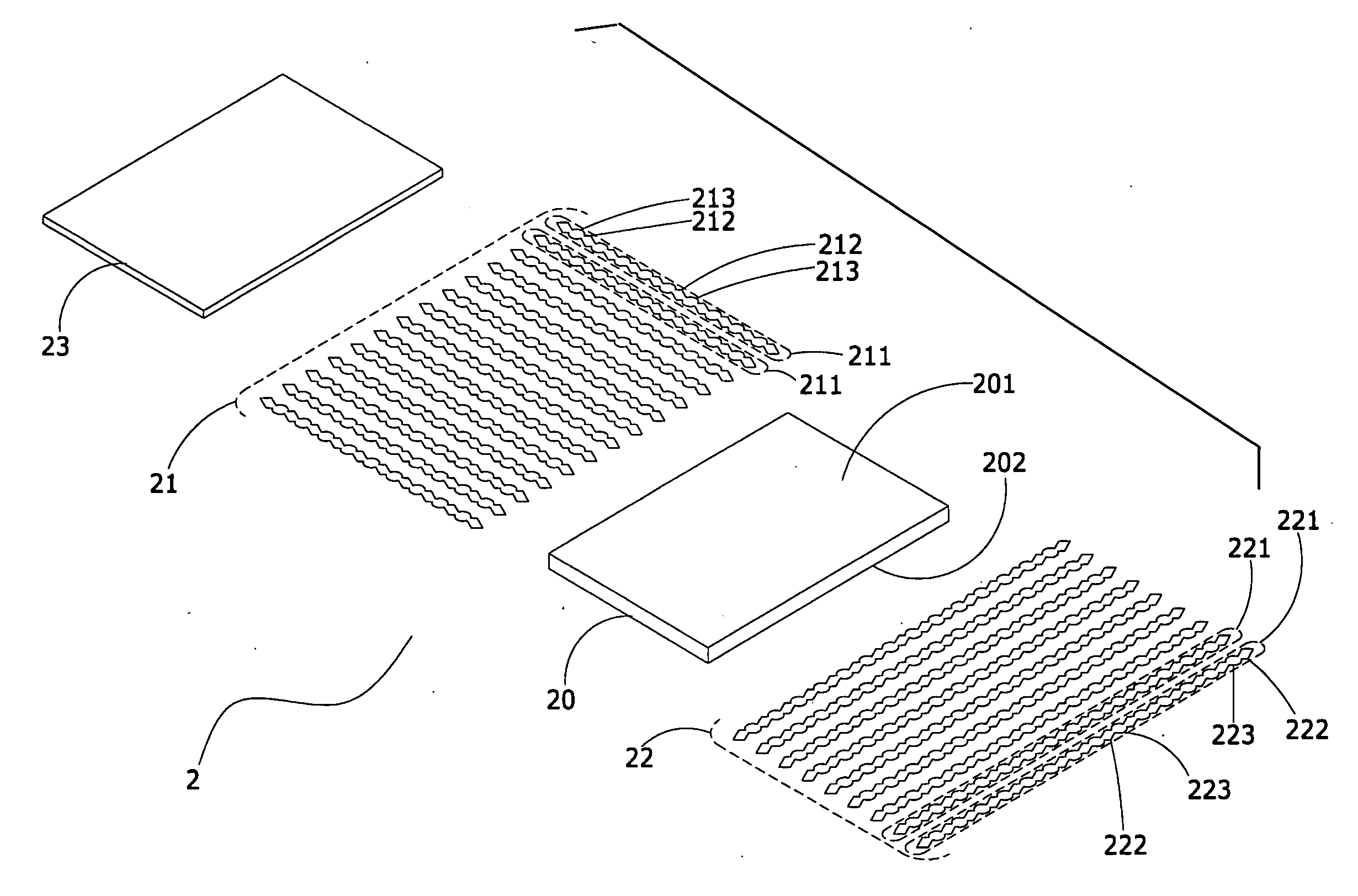
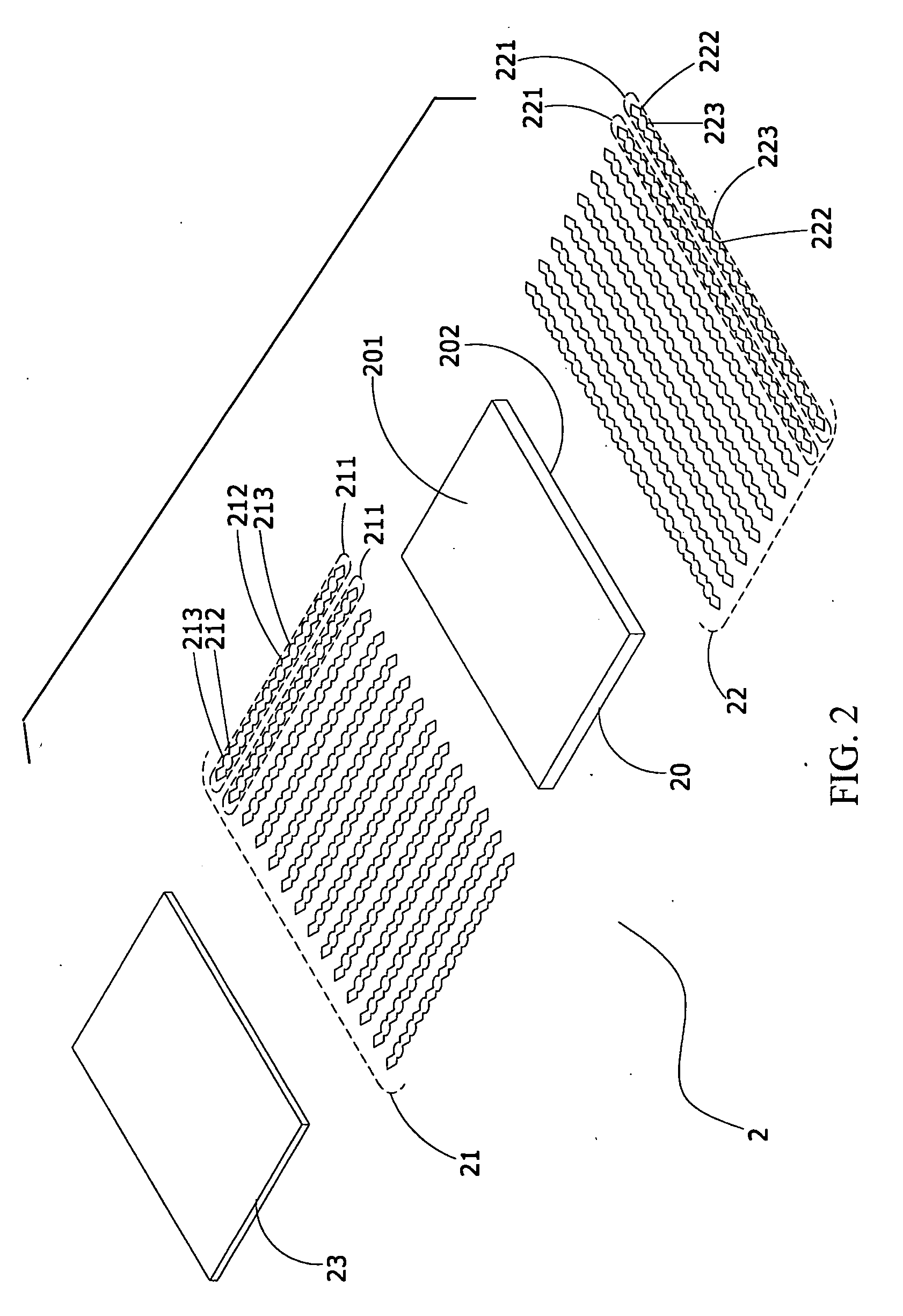
[0028]FIGS. 2 and 3 are a three-dimensional exploded view and a first partial schematic view of a preferred embodiment of the present invention respectively. As shown in FIGS. 2 and 3, the structural improvement to a touch panel of the present invention includes a touch panel 1, which has a substrate 20, a first induction layer 21, a second induction layer 22, and a protective layer 23.

[0029]The substrate 20 is made of a material of one of glass, poly carbonate (PC), ARTON, polyether sulfone (PES), ZEONOR, tri acetyl cellulose (TAC), polyethylene terephthalate (PET), or polymethyl methacrylate (PMMA). The substrate 20 has a first surface 201 and a second surface 202. When the first surface 201 is a top surface, the second surface 202 is a bottom surface. On the contrary, when the first surface 201 is a bottom surface, the s...


PUM


Abstract

A structural improvement to a touch panel is provided. comprising a substrate, and a first induction layer and a second induction layer are disposed on different surfaces of the substrate. said induction layers have a plurality of induction lines respectively. Each of the induction lines have a plurality of first induction blocks and second induction blocks having a same area respectively. said induction blocks are connected by first connection sections and second connection sections respectively. The first induction lines and the second induction lines are arranged alternately. said connection sections have a same area, and are in an overlapped area. Thereby, a blank area of the induction layers are reduced, and an induction area inside the touch panel is increased, so as to lower an optical contrast. Moreover, the connection sections have a capacity effect generating a same capacitance value, which prevents error determination or inaccuracy in touch control.

Description

BACKGROUND OF THE INVENTION[0001]1. Field of Invention[0002]The present invention relates to a touch panel, and more particularly to a structural improvement to a touch panel that increases an induction area inside the touch panel and reduces a blank area to lower an optical contrast.[0003]2. Related Art[0004]With the development of touch panel techniques, and improvement of product performance and component quality, various types of touch panels have been widely applied to various electronic products.[0005]FIG. 1 is a three-dimensional exploded view of a conventional touch panel. As shown in FIG. 1, a touch panel 1 has a substrate 10, an X-axis induction layer 11 and a Y-axis induction layer 12 are disposed on a top surface and a lower surface of the substrate 10 respectively. A plurality of X-axis induction lines 111 is arranged on the X-axis induction layer 11, and a plurality of Y-axis induction lines 121 is arranged on the Y-axis induction layer 12. The X-axis induction lines 1...

Claims


Application Information

Patent Timeline
IPC IPC(8): G06F3/041
CPCG06F2203/04111G06F3/044G06F3/0446G06F3/0445
Inventor WANG, KUEI MIN
Owner ETURBOTOUCH TECH
Why Eureka
Try Eureka