
Apparatus for driving electrophoretic display unit, electrophoretic apparatus, electronic device, and method of driving electrophoretic display unit

a technology of electrophoretic display unit and display unit, which is applied in the direction of electric digital data processing, instruments, computing, etc., can solve the problems of deteriorating display contrast of electrophoretic apparatus, inability to dispose of temperature sensor near solvent, and inability to drive electrophoretic display uni

Inactive Publication Date: 2010-08-19
SEIKO EPSON CORP
View PDF8 Cites 23 Cited by
  • Summary
  • Abstract
  • Description
  • Claims
  • Application Information

AI Technical Summary

Benefits of technology

[0010]In this case, a temperature equivalent value which changes depending on a solvent temperature is obtained, the driving control signal of the electrophoretic display unit is generated based on the temperature equivalent value, and a potential difference between the electrodes of the electrophoretic element is controlled without using a temperature sensor. As a result, since the temperature sensor becomes dispensable, it is possible to effectively use the limited volume of the apparatus. Since the temperature sensor is not used, it is possible to reduce the manufacturing cost. Particularly, if this configuration or method is applied to the semiconductor IC (integrated circuit), it would be advantageous from the viewpoint of volume efficiency as well as manufacturing cost.
[0016]In this case, instead of directly measuring the driving current, but a potential difference corresponding to the driving current of the electrophoretic display unit can be measured using the detection resistor and the potential difference detector. As a result, it is possible to inexpensively configure the current detector and the apparatus for driving the electrophoretic display unit having a simple configuration.
[0018]In a case where the detection resistor is disposed between the electrophoretic display unit and the ground potential as described above, it is possible to use a simple amplification circuit as the potential difference detector to simplify the configuration of the potential difference detector. In addition, it is possible to select more options regarding the circuit configuration.
[0020]In this case, since it is possible to operate using a detection value converted by the A / D converter into a digital value, the electrophoretic apparatus can be appropriately employed in digitally operable apparatuses. Further, it is possible to avoid increasing the number of analog components, which is easy to increase in size. As a result, it is possible to package the apparatus for driving the electrophoretic display unit within a limited packaging volume. Furthermore, it is possible to avoid increases in cost that may be caused by increasing the number of analog components.
[0028]According to a characteristic of the invention, since the conversion unit converts the detection value at an interval that is determined in advance, based on change of the response speed of the electrophoretic display corresponding to change of an atmospheric temperature, it is possible to prevent increases in power consumption caused by continuously performing the conversion.
[0030]In this case, since each characteristic of the aforementioned apparatus for driving the electrophoretic display unit is provided, it is possible to control a potential difference between the electrodes of the electrophoretic element by generating the driving control signal of the electrophoretic display unit based on the temperature equivalent value which changes depending on the solvent temperature without using a special temperature sensor. As a result, since the temperature sensor becomes dispensable, it is possible to reduce manufacturing cost of the electrophoretic apparatus or the entire electronic device.

Problems solved by technology

If the driving signal of the electrophoretic apparatus is inappropriate, the display contrast of the electrophoretic apparatus becomes deteriorated.
In this case, since the small-sized electronic device such as a wristwatch is configured within a limited packaging volume, it may be impossible to dispose the temperature sensor near the solvent in the electrophoretic display unit, which is a desired location to measure temperature.
Since the driving control signal of the electrophoretic display unit is generated based on the temperature measured by the temperature sensor, which is different from the actual solvent temperature, contrast of the electrophoretic display unit may be deteriorated.

Method used


Image

  • Apparatus for driving electrophoretic display unit, electrophoretic apparatus, electronic device, and method of driving electrophoretic display unit
  • Apparatus for driving electrophoretic display unit, electrophoretic apparatus, electronic device, and method of driving electrophoretic display unit
  • Apparatus for driving electrophoretic display unit, electrophoretic apparatus, electronic device, and method of driving electrophoretic display unit

Examples


first embodiment

Modified Example of First Embodiment

[0092]FIG. 8 illustrates a configuration of a modified example of a first embodiment of the invention. Referring to FIG. 8, in comparison with FIG. 3, it is understood that the location of the current detector 322 is modified.

[0093]According to this modified example, the current detector 322 is configured to detect the driving current flowing from the electrophoretic display unit 100 to the ground potential and outputs a detection value corresponding to the detected driving current. The configuration of the current detector 322 is basically equal to the first embodiment of the invention. In this configuration, the potential difference detected by the potential difference detector 326 is a driving current equivalent value which is proportional to the driving current. That is, since the conversion unit 323 can obtain the temperature equivalent value based on the detection value output from the potential difference detector 326, the functions of the ...

second embodiment

[0097]FIG. 9 illustrates a configuration of a driver unit 320 of an electrophoretic display unit 100 according to a second embodiment of the invention. Comparing first and second embodiments of the invention, the conversion unit 323 and the driving control signal generator 324 of the first embodiment correspond to the conversion unit 323b and the driving control signal generator 324b of the second embodiment, but their configurations and functions are different from each other. Other configurations and functions are similar between the first and second embodiments.

[0098]Referring to FIG. 9, the conversion unit 323b and the driving control signal generator 324b which are included in the driver unit 320 are different from those of the first embodiment as described above. The conversion unit 323b includes the A / D converter 327 and the cumulative average computing unit 328.

Conversion Unit 323b

[0099]The conversion unit 323b is configured to obtain a detection value detected by the curre...

third embodiment

[0105]FIG. 10 illustrates a configuration of an apparatus 320 for driving the electrophoretic display unit 100 according to a third embodiment of the invention. Comparing the first and third embodiments, the conversion unit 323 of the first embodiment is modified into a conversion unit 323c of the third embodiment. The configuration and function thereof are similar to those of the first embodiment.

Conversion Unit 323c

[0106]The conversion unit 323c is configured to obtain the detection value detected by the current detector 322 and convert it into the temperature equivalent value corresponding to the detection value. In this case, since the detection value is an analog value corresponding to the current equivalent value of the driving control signal, it is possible to obtain a voltage value by smoothing the current equivalent value using, for example, a low-pass filter circuit consisting of a condenser having a sufficient capacity and a resistor having a predetermined resistance val...


PUM


Abstract

An apparatus for driving an electrophoretic display unit includes: a current detector that detects a driving current supplied to or flowing out from the electrophoretic display unit and outputs a detection value corresponding to the driving current; a conversion unit that converts the detection value into a corresponding temperature equivalent value; and a driver that generates a driving control signal of the electrophoretic display unit based on the temperature equivalent value.

Description

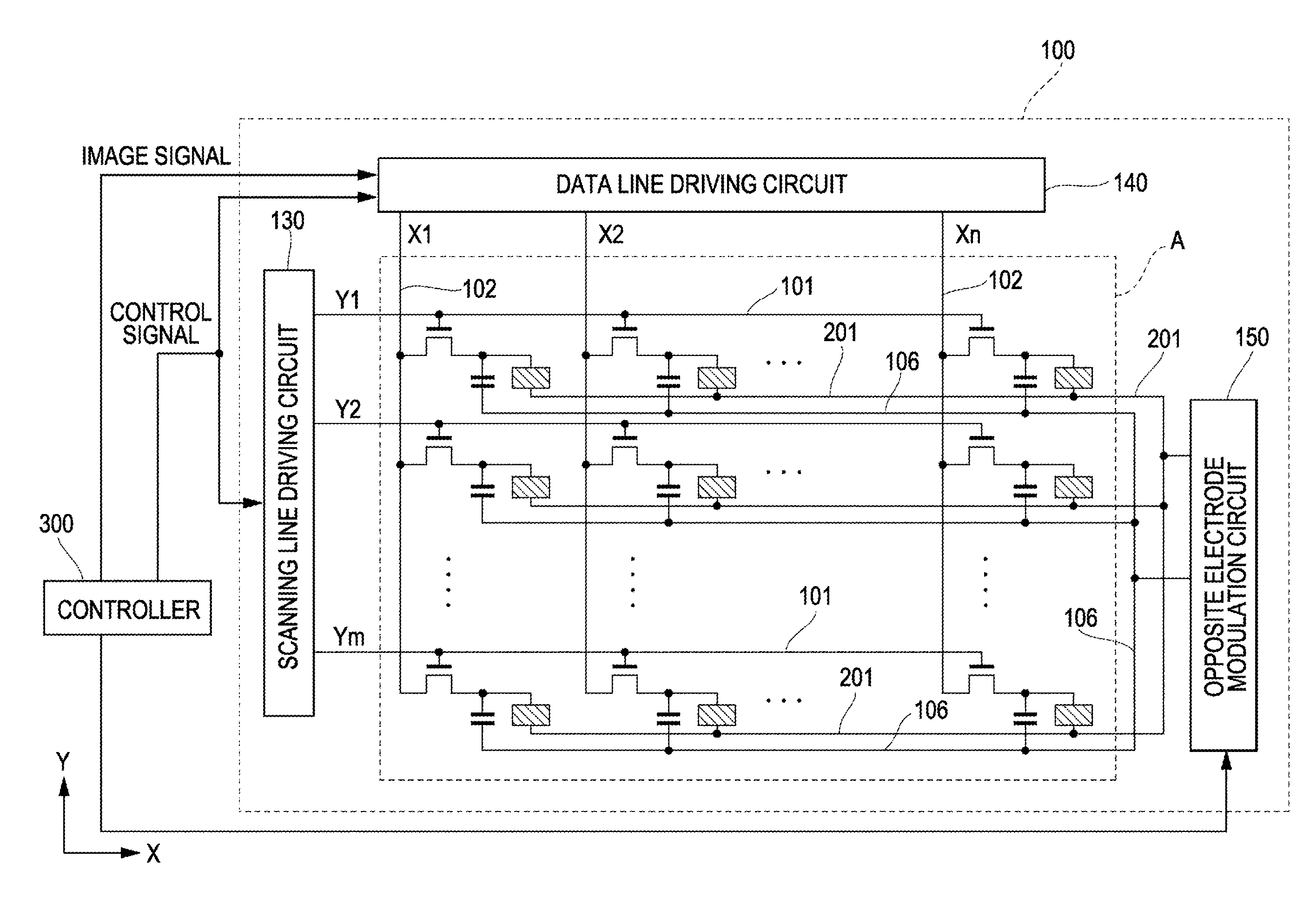
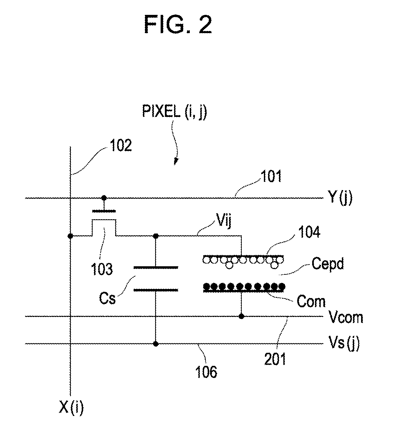
BACKGROUND[0001]1. Technical Field[0002]The present invention relates to an apparatus for driving an electrophoretic display unit, and more particularly, to an apparatus for driving an electrophoretic display unit embedded in a small-sized portable device such as a wristwatch.[0003]2. Related Art[0004]An electrophoretic apparatus is a device for displaying images by controlling a voltage applied between electrodes to control the movement of electrically-charged particles and change the colors of the external appearance. Recently, applications are being researched and developed to embed the electrophoretic apparatus into a small-sized portable device such as a wristwatch. The movement of the electrically-charged particles within the electrophoretic apparatus is influenced by the viscosity of a solvent. Since the viscosity of the solvent is highly dependent on temperature, it is necessary to use a driving signal having an optimal driving voltage and waveform depending on the temperatu...

Claims


Application Information

Patent Timeline
IPC IPC(8): G09G5/00G09G3/34
CPCG09G3/344G09G2320/041G09G2320/029
Inventor SAITO, HIDETOSHI
Owner SEIKO EPSON CORP
Learn More