Image encoding device, image encoding method, image decoding device, image decoding method, program, and storage medium

a technology of image encoding and image encoding, applied in the direction of signal generator with optical-mechanical scanning, color television with bandwidth reduction, etc., can solve the problems of residual data residual cost and decrease in prediction efficiency, so as to improve image quality, improve prediction mode estimation efficiency, and improve image quality

Active Publication Date: 2010-08-19
VELOS MEDIA LLC
View PDF19 Cites 135 Cited by
  • Summary
  • Abstract
  • Description
  • Claims
  • Application Information

AI Technical Summary

Benefits of technology

[0070]The present invention is accomplished in view of the above problem. A main object of the present invention is to provide an image encoding device, an image encoding method, a program, and a storage medium, each of which can carry out predictions from more various angles, thereby improving the efficiency in prediction. Further, another object of the present invention is to provide an image decoding device and an image decoding method, each of which decodes an image encoded by use of any of the image encoding device, the image encoding method, the program, and the storage medium.
[0135]With the above arrangement, it is possible to obtain the same effects as the sixth image decoding device according to the present invention.

Problems solved by technology

The intra prediction in the conventional image encoding device 300 causes a problem that efficiency in prediction decreases.
Further, a prediction residual cost of the prediction residual data F43 in (b) of FIG. 67 is “765”.

Method used


Image

  • Image encoding device, image encoding method, image decoding device, image decoding method, program, and storage medium
  • Image encoding device, image encoding method, image decoding device, image decoding method, program, and storage medium
  • Image encoding device, image encoding method, image decoding device, image decoding method, program, and storage medium

Examples


embodiment 1

[0291]An image encoding device according to the present invention will be described below as Embodiment 1 with reference to FIG. 1 through FIG. 13.

[0292](Arrangement of Image Encoding Device 100)

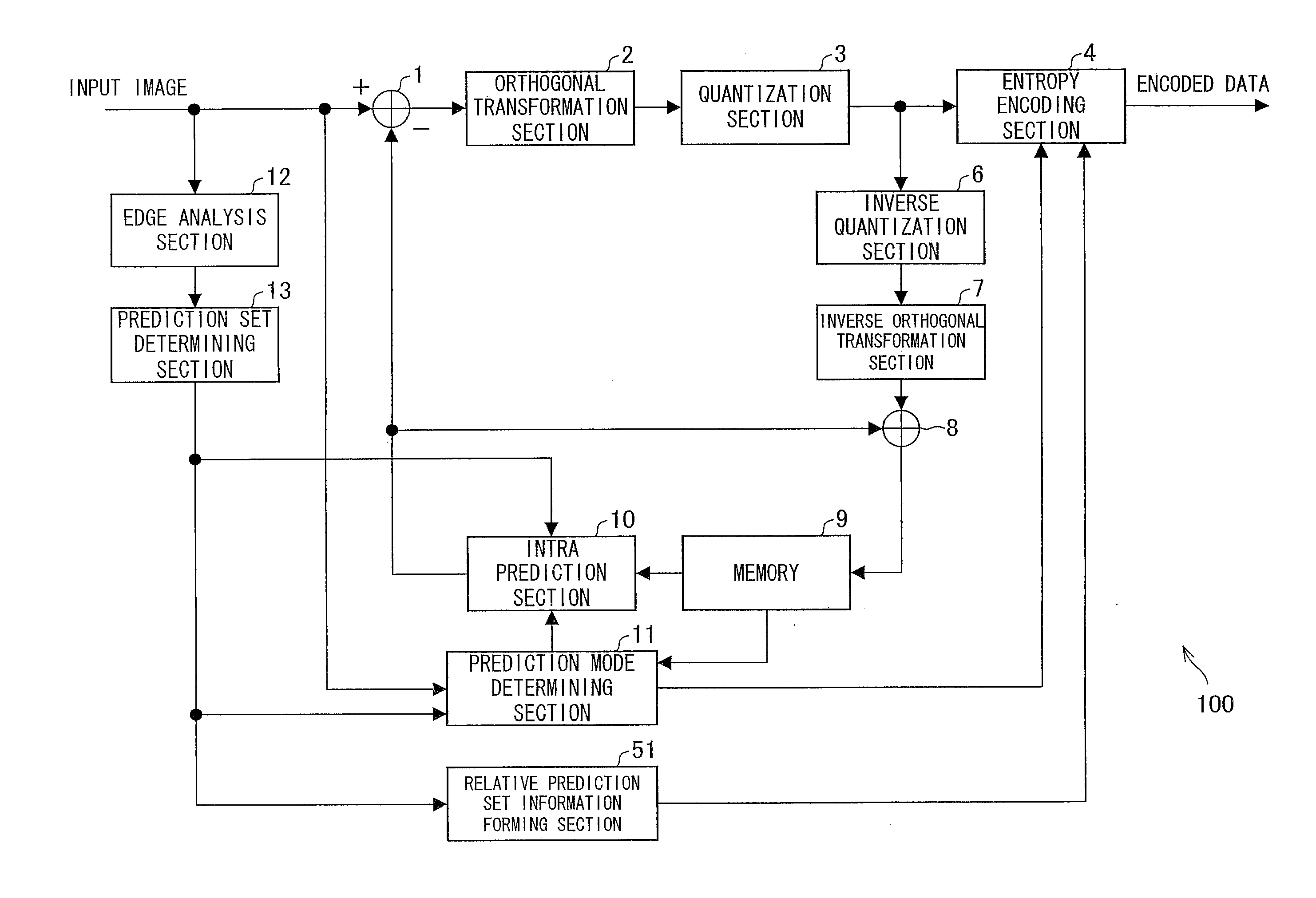
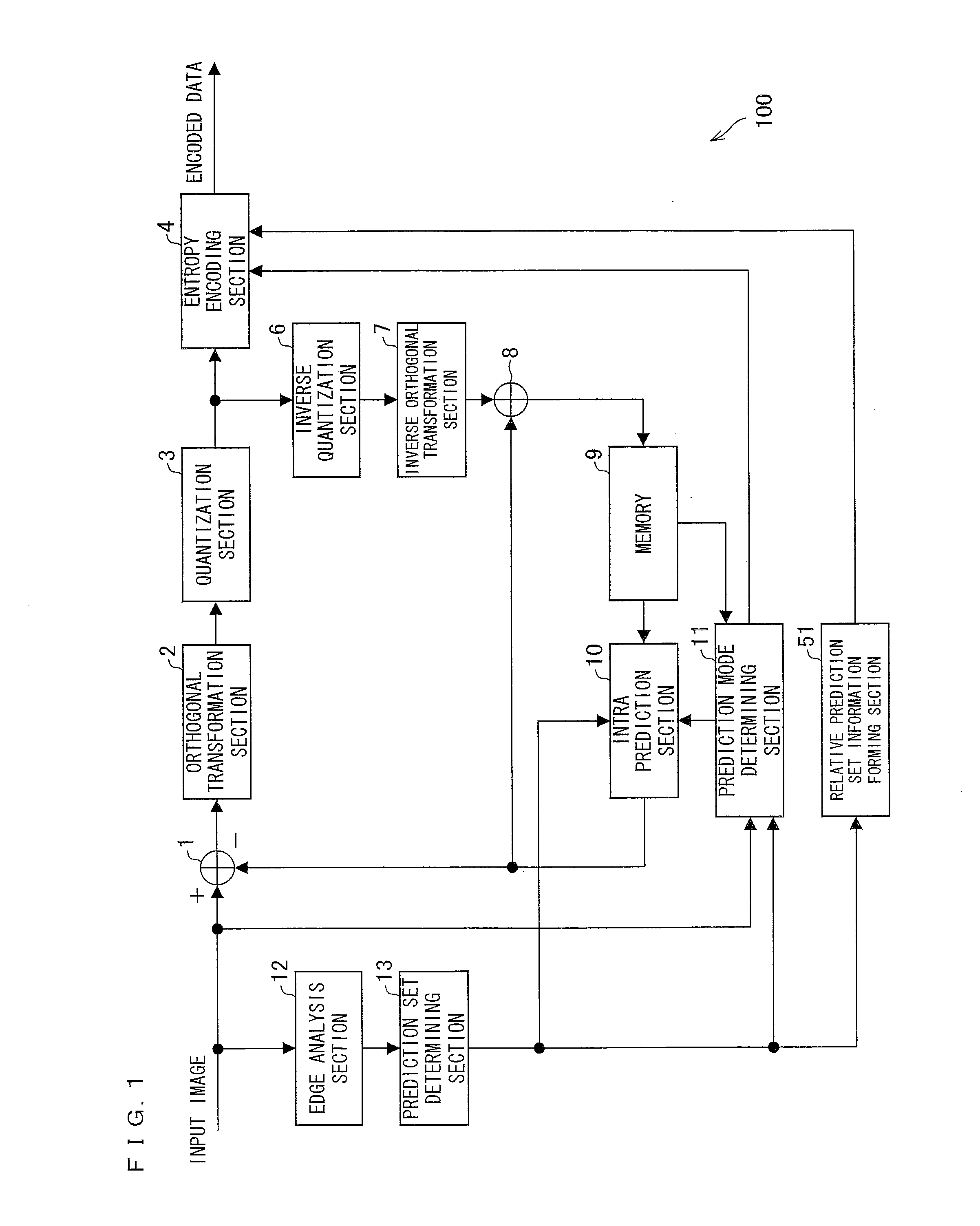
[0293]Initially, an arrangement of an image encoding device 100 according to the present embodiment will be described below with reference to FIG. 1. FIG. 1 is a block diagram showing the arrangement of the image encoding device 100 according to the present embodiment. The image encoding device 100 includes a difference computing section 1, an orthogonal transformation section 2, a quantization section 3, an entropy encoding section 4, an inverse quantization section 6, an inverse orthogonal transformation section 7, an addition computing section 8, a memory 9, an intra prediction section 10, a prediction mode determining section 11, an edge analysis section 12, a prediction set determining section 13, and a relative prediction set information forming section 51 (FIG. 1). The present embodim...

embodiment 2

[0412]An image decoding device according to the present invention is described below as Embodiment 2, with reference to FIG. 14 through FIG. 17. The same constituent components as in Embodiment 1 have the same reference signs as in Embodiment 1, and are not explained here.

[0413](Arrangement of Image Decoding Device 150)

[0414]An arrangement of an image decoding device 150 according to Embodiment 2 is explained below with reference to FIG. 14. FIG. 14 is a block diagram showing the arrangement of the image decoding device 150.

[0415]As shown in FIG. 14, the image decoding device 150 mainly includes an entropy decoding section 5, an inverse quantization section 6, an inverse orthogonal transformation section 7, an addition computing section 8, a memory 9, an intra prediction section 10, and a prediction set information forming section 52. In the present embodiment, only the entropy decoding section 5 and the prediction set information forming section 52, which have not been described ye...

embodiment 3

[0454]Another embodiment of the image encoding device according to the present invention is explained below as Embodiment 3, with reference to FIG. 18 through FIG. 25. The same constituent components as in Embodiments 1 and 2 have the same reference signs as in Embodiments 1 and 2, and are not explained here. Embodiment 1 describes an image encoding device in which the prediction set is changed per predetermined pixel block unit according to an edge orientation of a target block to be encoded, so that the image encoding device can carry out more various predictions than the conventional technique. Embodiment 3 deals with an image encoding device (i) which forms prediction sets in each of which a combination of prediction modes is automatically determined in accordance with an image and (ii) which selects a prediction set from the prediction sets thus formed, according to an edge orientation of a target block to be encoded, so that the image encoding device can further improve effici...


PUM


Abstract

A prediction set determining section (13) selects a prediction set from a prediction set group including a plurality of prediction sets having different combinations of prediction modes corresponding to different prediction directions. Further, a prediction mode determining section (11) selects a prediction mode from the prediction set thus selected. An entropy encoding section (4) encodes the prediction set thus selected, the prediction mode thus selected, and residual data between an input image and a predicted image formed on the basis of the prediction set and the prediction mode. This allows an image encoding device to carry out predictions from more various angles, thereby improving prediction efficiency.

Description

TECHNICAL FIELD[0001]The present invention relates to an image encoding device, an image encoding method, a program, and a storage medium, each for encoding an image. The present invention also relates to an image decoding device, an image decoding method, a program, and a storage medium, each for decoding an encoded image.BACKGROUND ART[0002]Image encoding techniques have been applied to many video devices that are familiarly used. Target products to which the techniques are applied may be, for example, DVD for enjoying video contents, such as movies, hard disk recorders in which video contents, such as TV broadcasts, are to be recorded, digital TV encoding systems, DVD cameras, and mobile phones that can carry out image processing. As such, the image encoding techniques are applied very widely.[0003]Non Patent Literature 1 discloses (i) an image encoding device that encodes an image by use of a spatial correlation or a temporal correlation in the image, and (ii) an image decoding ...

Claims


Application Information

Patent Timeline
Patent Type & Authority Applications(United States)
IPC IPC(8): H04N7/32H04N19/593
CPCH04N19/593H04N19/19H04N19/00763H04N19/176H04N19/174H04N19/103H04N19/61H04N19/139H04N19/159
Inventor TSUKUBA, TAKESHITOKUMO, YASUAKI
Owner VELOS MEDIA LLC
Why Eureka
Try Eureka