Balloon catheter inflation apparatus and methods

a balloon catheter and inflation apparatus technology, applied in balloon catheters, medical science, surgery, etc., can solve the problems of not responding, many of the devices used in these treatments are bulky and cumbersome to use, and the existing inflation devices are bulky and cumbersome to work

Active Publication Date: 2010-08-19
ENTELLUS MEDICAL
View PDF8 Cites 151 Cited by
  • Summary
  • Abstract
  • Description
  • Claims
  • Application Information

AI Technical Summary

Problems solved by technology

Though many instances of sinusitis may be treatable with appropriate medicates, in some cases sinusitis persists for months or more, a condition called chronic sinusitis, and may not respond to medical therapy.
Many of these devices used in these treatments have been bulky and cumbersome to use.
As a result, ...

Method used


Image

  • Balloon catheter inflation apparatus and methods
  • Balloon catheter inflation apparatus and methods
  • Balloon catheter inflation apparatus and methods

Examples


Embodiment Construction

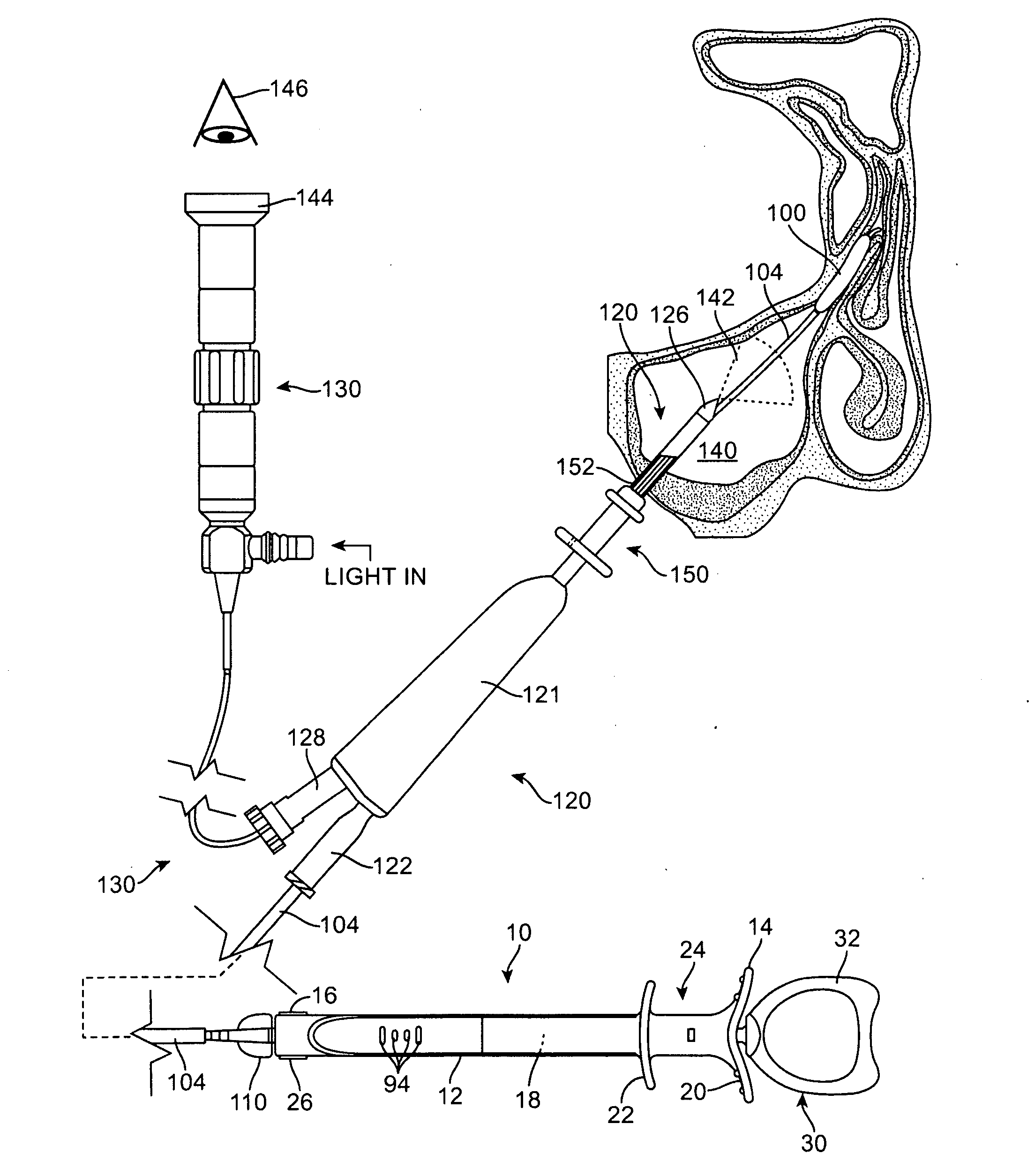
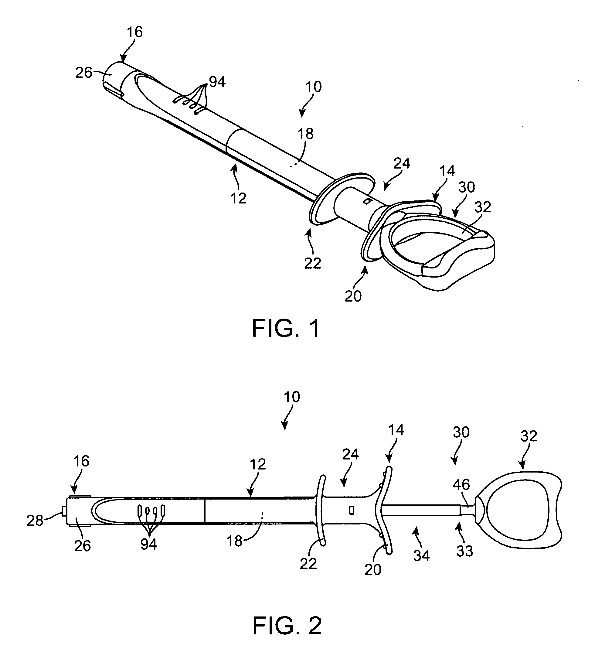
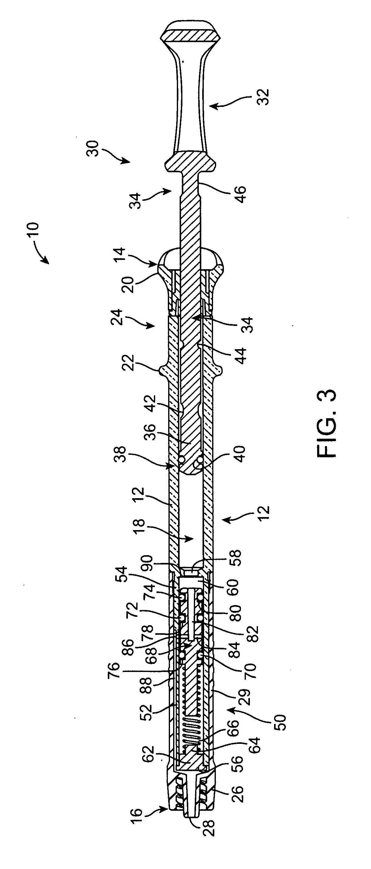
[0024]FIGS. 1 and 2 illustrate a inflation device 10 that is used to dilate or inflate an expandable member such as a dilation balloon 100 (illustrated in FIGS. 10-12) that is disposed on a distal end of an elongate member 102 (also illustrated in FIGS. 10-12) such as a balloon catheter 104. The inflation device 10 is configured as an actuator that is used to selectively push or pull a substantially incompressible fluid into or out of the dilation balloon 100. The inflation device 10 may take the form of a syringe or the like. For example, in the embodiment illustrated in FIGS. 1 and 2, the inflation device 10 includes a syringe body 12 that includes a proximal end 14, a distal end 16, and a central bore 18 (better seen in FIGS. 3-5, 6A, 6B, and 7-9). The syringe body 12 is typically made from a polymer material such as polycarbonate or other plastic-based materials although a variety of materials may be used. The shape of the syringe body 12 is typically cylindrical although the in...


PUM


Abstract

An inflation device includes a syringe body containing a bore. The bore holds a fluid that is used to inflate a separate device such as a dilation balloon. A plunger assembly slides within the syringe bore and contains a sealing member that forms a fluid tight seal with the syringe body. A shut-off valve is disposed within the distal end of the syringe body. The distal end of the syringe body has a fluid bypass channel fluidically coupled to the aperture of a connector. The shut-off valve has a spring-biased moveable piston with a bypass lumen contained therein, wherein the bypass lumen forms a fluid path between the bore and the fluid bypass channel when the pressure of the fluid is below a threshold value. The fluid path between the bore and the fluid bypass channel is interrupted when the pressure of the fluid is above the threshold value.

Description

FIELD OF THE INVENTION[0001]The field of the invention generally relates to balloon inflation devices and methods. Balloon inflation devices are typically used in constricted spaces within the human or mammalian body. Balloon dilation has become popular in numerous medical fields of application. One particular use of balloon dilation in the treatment of sinusitis.BACKGROUND OF THE INVENTION[0002]Sinusitis is a condition affecting over 35 million Americans, and similarly large populations in the rest of the developed world. Sinusitis occurs when one or more of the four paired sinus cavities (i.e., maxillary, ethmoid, frontal, sphenoid) becomes obstructed. Normally the sinus cavities, each of which are lined by mucosa, produce mucous which is then moved by beating cilia from the sinus cavity out to the nasal cavity and down the throat. The combined sinuses produce approximately one liter of mucous daily, so the effective transport of this mucous is important to sinus health.[0003]Each...

Claims


Application Information

Patent Timeline
IPC IPC(8): A61M25/10A61B1/00A61F2/958
CPCA61M25/1018A61B17/24A61M39/22A61M29/02A61M25/10182A61M25/10185A61M25/10187A61M39/12A61M2039/1033A61M2210/0618
Inventor LESCH, JR., PAUL R.VAJGRT, PAUL A.PETRICK, TIMOTHY B.
Owner ENTELLUS MEDICAL
Why Eureka
Try Eureka