
Interactive Graphical User Interface for an Internet Site Providing Data Related to Radio Frequency Emitters

a technology of radio frequency emitter and internet site, applied in the field of information system, can solve the problems of public danger, danger to field workers and certain parts of the general public, and achieve the effect of saving labor

Inactive Publication Date: 2010-08-19
RF CHECK INC
View PDF26 Cites 14 Cited by
  • Summary
  • Abstract
  • Description
  • Claims
  • Application Information

AI Technical Summary

Benefits of technology

The GUI effectively addresses the safety concerns by providing comprehensive RF emission data, enabling users to assess and mitigate exposure risks, reduce labor costs, and ensure safer working conditions for field workers by consolidating data from multiple sources and allowing for power-down requests.

Problems solved by technology

It is presently recognized that the quickly expanding public cell telephone network of RF emitters installed by a growing number of host companies presents a public danger due to RF radiation.
Although it is clear that the current frequency ranges and power levels of such emissions, and the physical locations of associated emitters, i.e., transmitting antennae, generally are not presently considered to pose a danger to the public, it is also clear that a danger does exist to field workers and to certain portions of the general public.
As a key point, graphic representation of MPE studies, information about RF emissions, frequencies, power levels, special coordinates, etc., from any one antenna is available, if not elsewhere, at least from the corresponding broadcaster, however, since many antennae support towers and similar support elements are used by competing broadcasters, the composite effect of transmission from such locations is not known or knowable except by the accumulation of the individual data from each of the broadcasters in one place and the utilization of standard and well known calculations for the determination of the composite effect, which may be far more dangerous to personnel proximate such locations than the effect from any one broadcaster's emissions.

Method used


Image

  • Interactive Graphical User Interface for an Internet Site Providing Data Related to Radio Frequency Emitters
  • Interactive Graphical User Interface for an Internet Site Providing Data Related to Radio Frequency Emitters
  • Interactive Graphical User Interface for an Internet Site Providing Data Related to Radio Frequency Emitters

Examples


Embodiment Construction

[0042]The above described drawing figures illustrate the present invention in at least one of its preferred, best mode embodiments, which is further defined in detail in the following description. Those having ordinary skill in the art may be able to make alterations and modifications in the present invention without departing from its spirit and scope. Therefore, it must be understood that the illustrated embodiments have been set forth only for the purposes of example and that they should not be taken as limiting the invention as defined in the following.

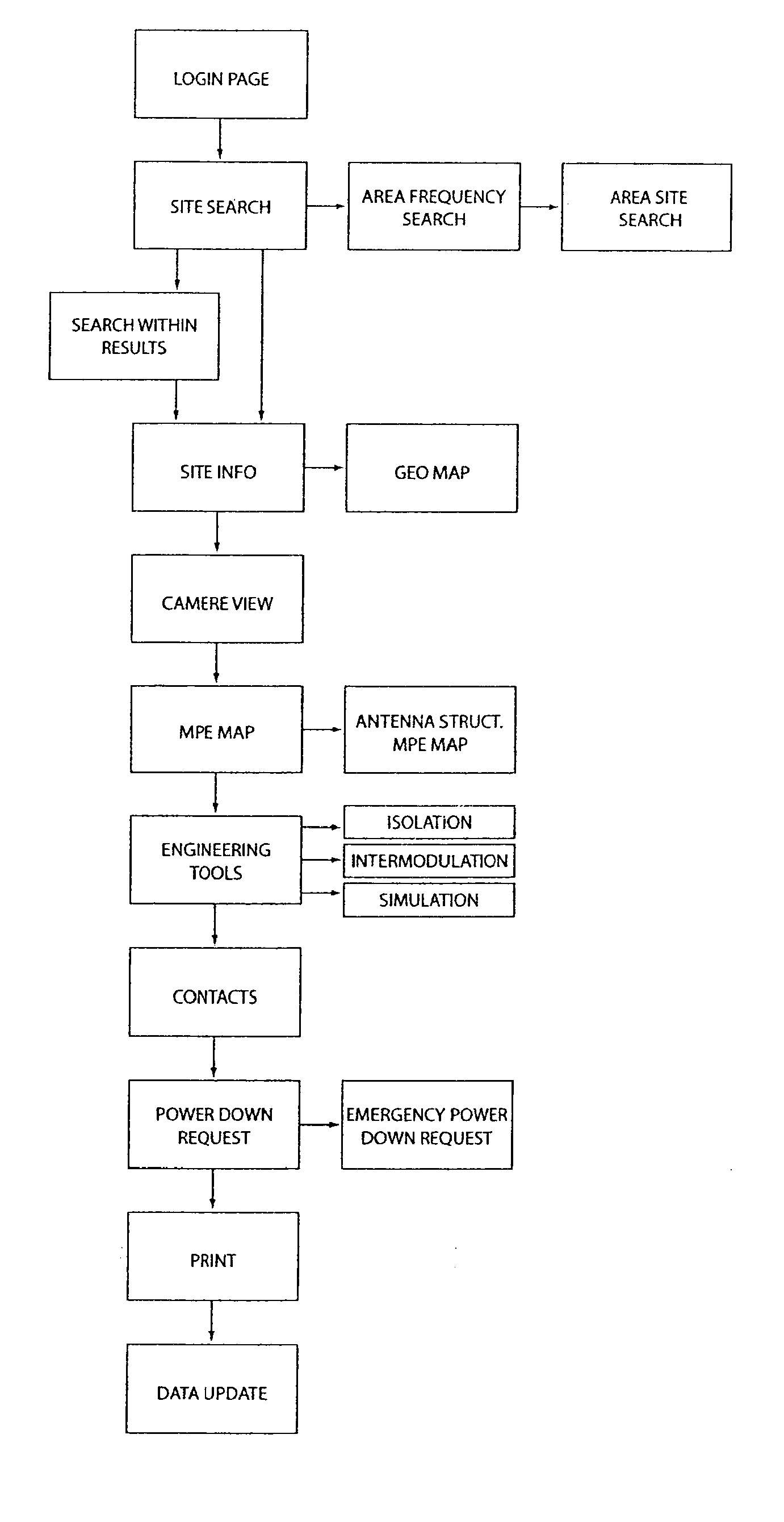
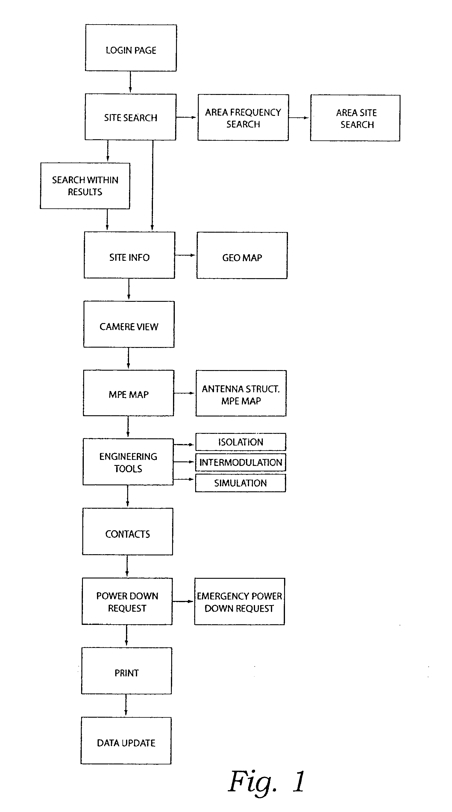
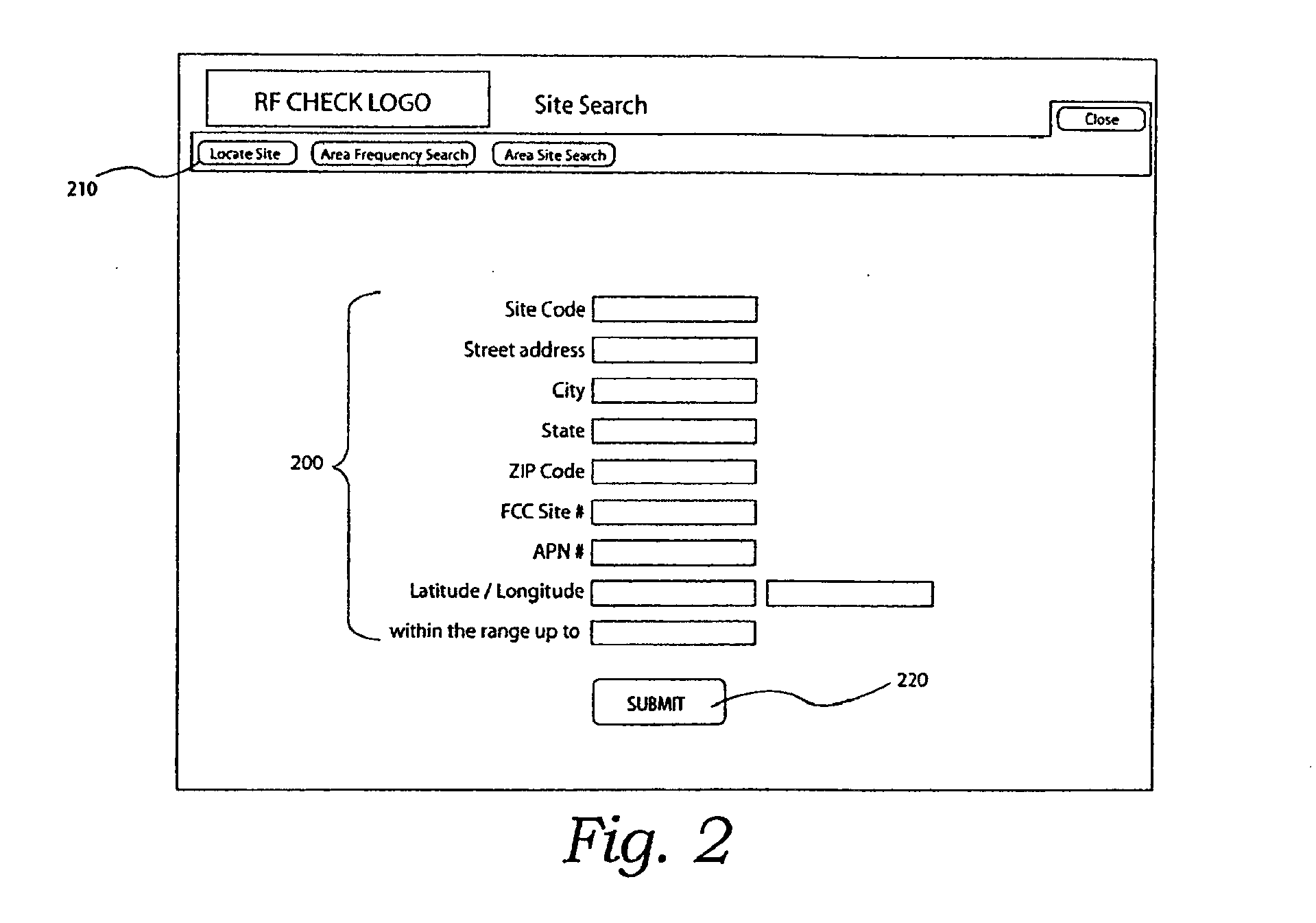
[0043]In a preferred embodiment of the present invention, as shown in FIG. 1, a user accesses the software application via the GUI by providing a valid user name and password as is well known in the art. By default the application displays a site search screen. See FIG. 2A, a schematic diagram of the access screen, and FIG. 2B, a picture of the actual screen. From this screen a user input the necessary information to the applicati...


PUM


Abstract

An interactive graphical user interface adapted for receiving user power down requests and for providing data related to RF emitter sites through a plurality of logically interrelated and interactive graphical monitor screens including: a search screen presenting plural location criteria for the sites, and adapted for receiving location requests; an information screen having a plan view MPE map; a wide area aerial map; a photographic camera view; and a list of site facts; a contacts screen presenting information about the RF emitters on a selected site, including an identity a broadcaster, owner, property manager, and municipal entity; and a request screen adapted for accepting, for a selected RF emitter, a power down request.

Description

RELATED APPLICATIONS[0001]This application claims priority to and is a Continuation of U.S. application Ser. No. 11 / 100,947 filed Apr. 6, 2005, which is a Continuation-In-Part of U.S. application Ser. No. 10 / 215,495 filed Aug. 8, 2002 and entitled: Composite Energy Emission Information System For Improved Safety To Site Personnel, both of which are incorporated herein by reference in their entirety.BACKGROUND OF THE INVENTION[0002]1. Field of the Invention[0003]This invention relates generally to information systems concerned the public exposure to RF emissions and more particularly to a graphical user interface for interaction with such an information system.[0004]2. Description of Related Art[0005]The following art defines the present state of this field and each of the following U.S. disclosures is hereby incorporated herein by reference:[0006]Douglas et al., U.S. Pub. 2003 / 0069648, relates to a system and method for tracking, monitoring, and managing equipment. An embodiment of ...

Claims


Application Information

Patent Timeline
Patent Type & Authority Applications(United States)
IPC IPC(8): G06F3/048H04B17/00H04W16/18
CPCH04W16/18G06Q50/265Y02P90/845Y02D30/70
Inventor WILLIAMS
Owner RF CHECK INC
Learn More