[0018]According to the aspect of the present invention according to claim 1, since the top film is applied to come into
close contact with the projections and depressions formed by the LED elements, air can be prevented from being trapped (to form an
air cavity) in the space between the LED elements and the top film. Therefore, the force to secure the LED elements can be increased, and the LED elements less susceptible to external heat. If an
air cavity occurs, the air can expand due to external heat to cause the LED elements to slightly move (rattle). In this case (if the LED elements rattle), the force to secure the LED elements can decrease, and the LED elements can be detached from the substrate. However, the present invention eliminates the concern. Since no
air cavity occurs, non-uniform
diffuse reflection by air also does not occur, and thus, the appearance of the surface emitter is improved.
[0022]According to the aspect of the present invention according to claim 4, the electric wiring is a mesh-shaped circuit. Thus, even if the electric wiring is partially
cut out, the remaining LED elements can be energized through a path bypassing the cutout part and turned on and off. Therefore, in the case where the surface emitter is used as an interior material for a building, a part of the surface emitter (one unit) can be appropriately
cut out to accommodate a receptacle or the like, and thus, the workability of the surface emitter is significantly improved. Of course, the surface emitter can be installed at an internal corner or an external corner.
[0020]According to the aspect of the present invention according to claim 3, the top film is a highly clingy and highly stretchable
polyvinyl chloride film. The combination of the highly clingy and highly stretchable
polyvinyl chloride film and the
vacuum pressure bonding described above allows the top film to come into
close contact with the projections and depressions formed by the LED elements with higher reliability, improves the waterproofness of the surface emitter, and increases the force to secure the LED elements.
[0021]The highly clingy and highly stretchable
polyvinyl chloride film (a 100-micron film manufactured by HIROSHIMA KASEI, LTD., for example) has no pinhole in the material and thus can be considered as making a large contribution to the improvement of the waterproofness. More specifically, since the film has no pinhole, the film disposed on the substrate in a stretched manner can prevent water from entering (penetrating to) the side of the LED elements from the outside with high reliability, thereby significantly improving the waterproofness. In a test carried out by the applicant in which the surface emitter with the film is immersed in water for four months, it has been confirmed that penetration of water into the surface emitter does not occur, and the surface emitter has high waterproofness. Thus, the surface emitter can be installed outdoors or at a place where the surface emitter gets wet (on a wall of a bathroom, for example) without being housed in a case (housing) or the like (that is, in an exposed manner). Thus, the surface emitter can have a wide variety of extremely novel applications and can have many product variations.
[0022]According to the aspect of the present invention according to claim 4, the electric wiring is a mesh-shaped circuit. Thus, even if the electric wiring is partially
cut out, the remaining LED elements can be energized through a path bypassing the cutout part and turned on and off. Therefore, in the case where the surface emitter is used as an interior material for a building, a part of the surface emitter (one unit) can be appropriately cut out to accommodate a receptacle or the like, and thus, the workability of the surface emitter is significantly improved. Of course, the surface emitter can be installed at an internal corner or an external corner.
[0023]Although LED elements generally have a long life, they
burn out once in a while. According to the present invention, even when an LED element burns out, the other LED elements can be kept lighting. Many of the conventional surface emitters have electric wiring that turns off all the LED elements or part of the LED elements (a row of LED elements, for example) including the burnt out one when one LED element burns out.
[0027]The “printed material” described in claim 5 is not limited to a top film on which an appropriate pattern is previously printed but may be a top film on which an appropriate pattern is printed after
vacuum pressure bonding.
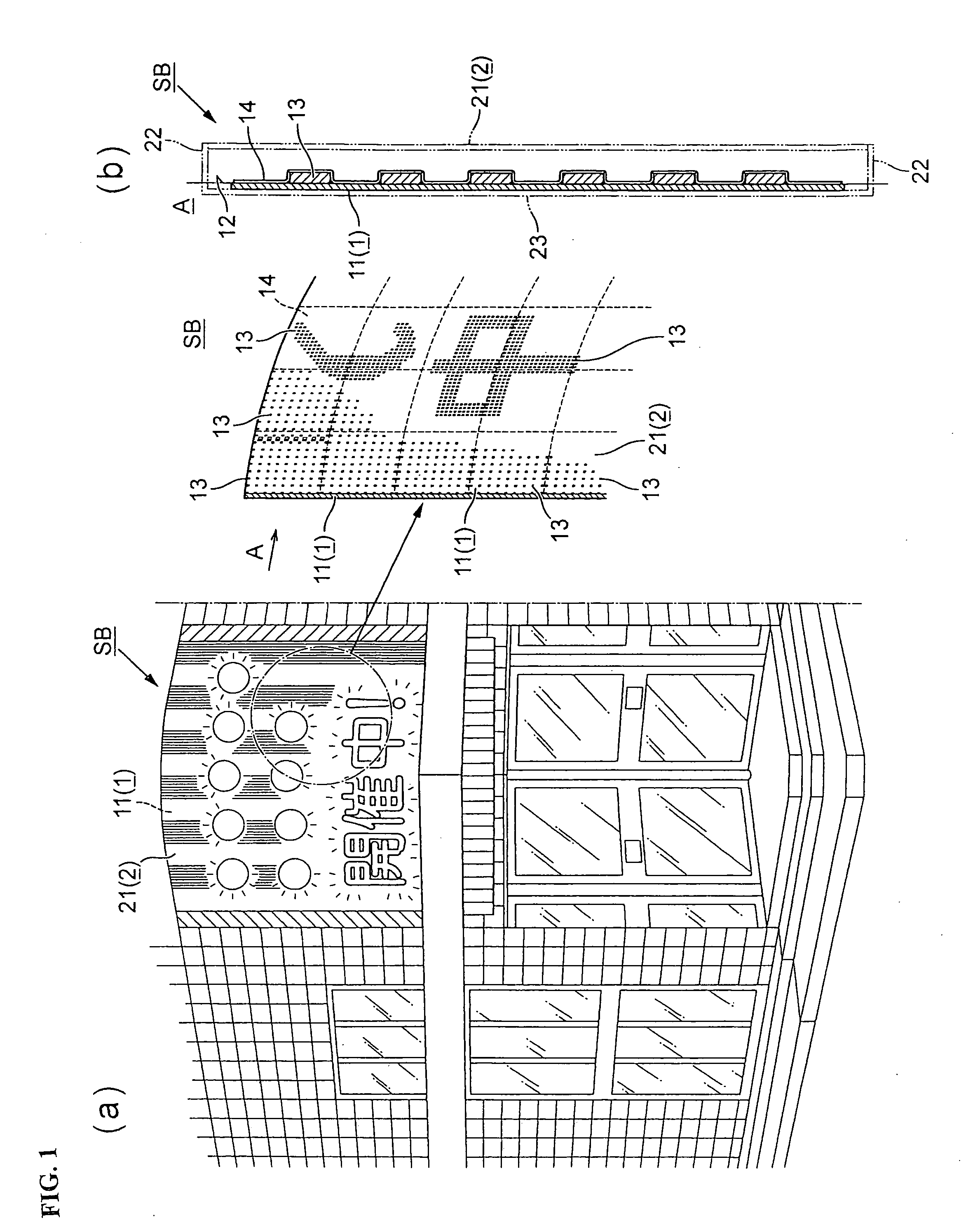
[0028]According to the aspect of the present invention according to claim 6, the internally illuminated sign incorporates the surface emitter according to any of claims 1 to 5. Thus, the internally illuminated sign has a good appearance and a small thickness (thin decorative lighting). That is, dots of the LEDs elements are invisible, and the thin decorative lighting emits light with uniform brightness. The thin decorative lighting can be safely installed anywhere because it does not obstruct pedestrians or hit a child in the head. In addition, since the surface emitter itself has high waterproofness, the thin decorative lighting is also highly waterproof and can be installed at a place where the waterproofness of the sign case can hardly be ensured because of the shape of the wall of the building on which the sign is installed, for example.

