Optical fiber manufacturing methods

a technology of optical fiber and manufacturing method, applied in the field of optical fiber manufacturing method, can solve the problems of high initial investment and maintenance fees, other significant costs incurred in recycling, and relatively expensive helium gas, and achieve the effect of less modification and simple system

Inactive Publication Date: 2010-08-26
FURUKAWA ELECTRIC CO LTD
View PDF15 Cites 3 Cited by
  • Summary
  • Abstract
  • Description
  • Claims
  • Application Information

AI Technical Summary

Benefits of technology

[0007]The present invention discloses an optical fiber manufacturing method, which recycles cooling gas (such as helium) with a simple system (less modification from a conventional device).

Problems solved by technology

However, because helium is a relatively expensive gas compared with other gases, several methods to recycle high-purity helium by filtering used helium through filters or refining equipment have been proposed.
However, the methods disclosed in U.S. Pat. No. 5,890,376 and Japanese Patent Application Laid-open No. 2004-142976 require large complicated systems, and lead to high initial investment and maintenance fees.
Therefore, other significant costs are incurred when recycling is used to reduce the cost of helium.

Method used


Image

  • Optical fiber manufacturing methods
  • Optical fiber manufacturing methods
  • Optical fiber manufacturing methods

Examples


embodiment

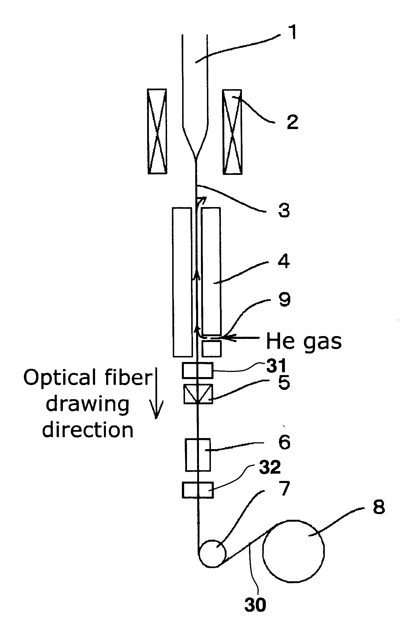
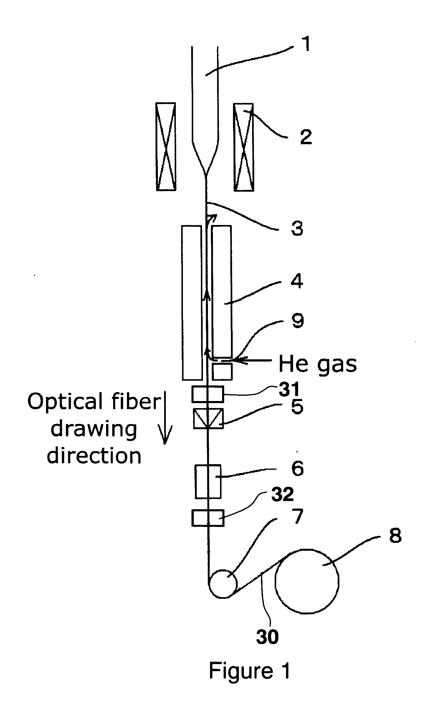
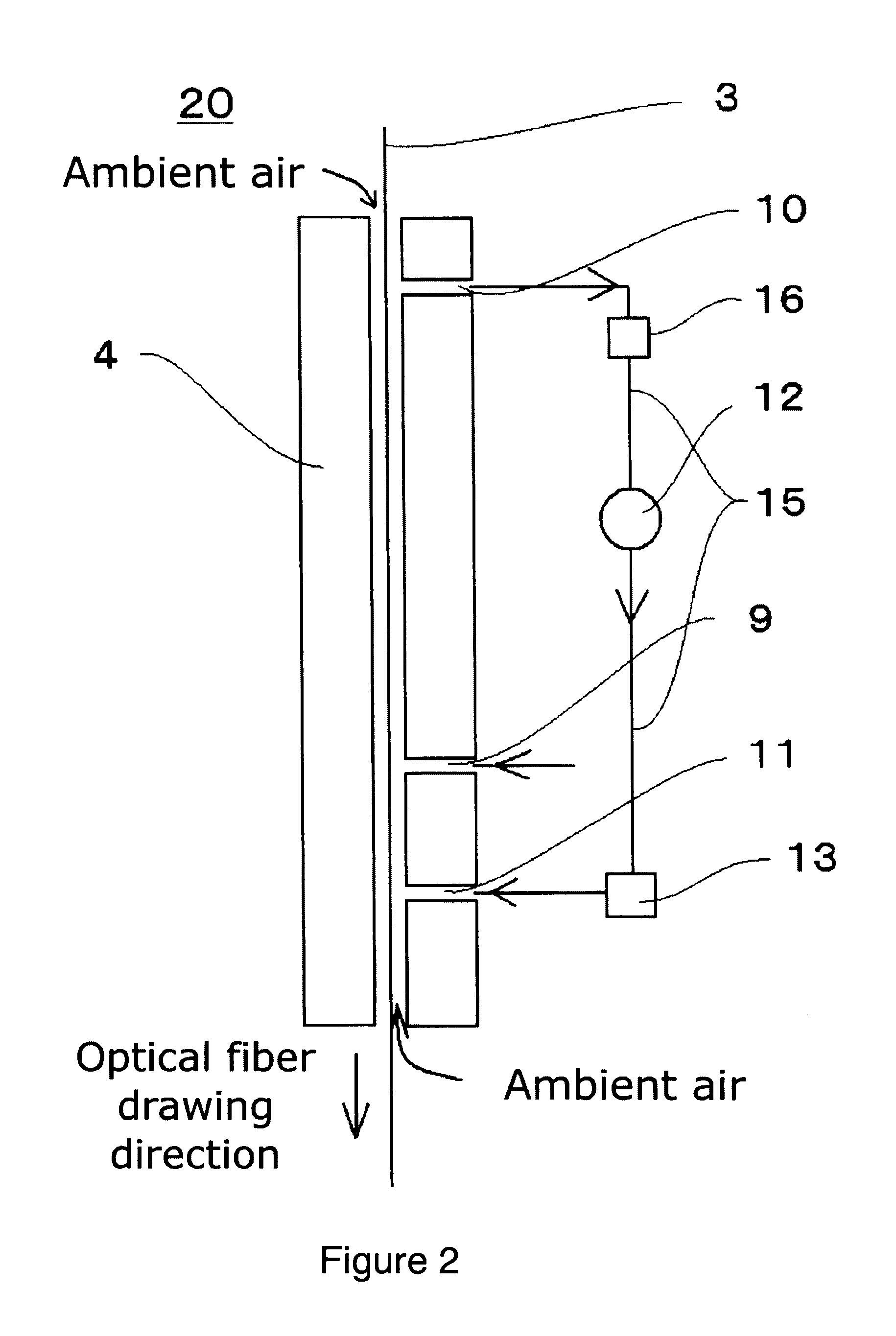
[0028]As an embodiment, a glass fiber is cooled down and a coating layer is applied by using the optical fiber cooling system disclosed in FIG. 2. The results are shown below. In this embodiment, the amount of the high-purity helium is controlled while keeping the amount of the recovered cooling gas constant in order to obtain a predetermined outer diameter of the coated optical fiber. Also, the speed of optical fiber drawing is 1200 m / minute.

[0029]If no cooling gas is recovered from the cooling-gas-recovery port 10, then the predetermined outer diameter of the optical fiber is obtained when the high-purity helium is supplied 29 L / minute from the cooling gas supply port. If the amount of the recovered cooling gas increases to 20, 35, 50 or 60 L / minute, then the supplied amount of the high-purity helium from the cooling-gas-supply port 9 is 18, 13, 12 or 23 L / minute respectively to obtain the predetermined outer diameter of the optical fiber. Also, the amount of the recovered cooling...


PUM

PropertyMeasurementUnit
outer diameteraaaaaaaaaa
concentrationaaaaaaaaaa
temperatureaaaaaaaaaa

Abstract

An optical fiber manufacturing method, which recycles cooling gas with a simple system (less modification from a conventional device) is provided. The method comprises the steps of heating and melting an optical fiber preform, cooling the glass fiber obtained from the preform using a cooling device, and coating the cooled glass fiber with a coating material. During the cooling step, cooling gas is supplied from the bottom portion of the cooling device 4; a part of the cooling gas in the cooling device 4 is recovered from the top portion of the cooling device 4; and the recovered gas is re-supplied from the bottom portion of the cooling device 4.

Description

CROSS-REFERENCES TO RELATED APPLICATIONS[0001]This application claims the benefit of priority from Japanese Patent Application No. 2009-039545 filed Feb. 23, 2009, the entire contents of which is incorporated herein by reference.TECHNICAL FIELD[0002]The present invention relates to optical fiber manufacturing methods; more particularly, it relates to methods to cool down optical fibers drawn from an optical fiber preform.BACKGROUND OF THE INVENTION[0003]A conventional optical fiber manufacturing method is explained using FIG. 1. An optical fiber 30 is manufactured by drawing a glass fiber 3 from an optical fiber preform 1, which is heated and melted in a heating furnace 2. The drawn glass fiber 3 is cooled down to a predetermined temperature using cooling gas in a cooling device 4; coating material is applied to the glass fiber 3 by a die 5; and the coating material is cured by a resin-cure oven 6. Then, the optical fiber 30 is taken up by a take-up winder 8 via capstan 7. The outer...

Claims


Application Information

Patent Timeline
Patent Type & Authority Applications(United States)
IPC IPC(8): C03B37/023
CPCC03B2205/61C03B37/02718Y02P40/57
Inventor SUZUKI, TAKASHIKURASEKO, HIROSHIORITA, NOBUAKI
Owner FURUKAWA ELECTRIC CO LTD
Why Eureka
Try Eureka