
Field Level Tracker Controller

Inactive Publication Date: 2010-08-26
SUMITOMO ELECTRIC IND LTD
View PDF11 Cites 39 Cited by
  • Summary
  • Abstract
  • Description
  • Claims
  • Application Information

AI Technical Summary

Benefits of technology

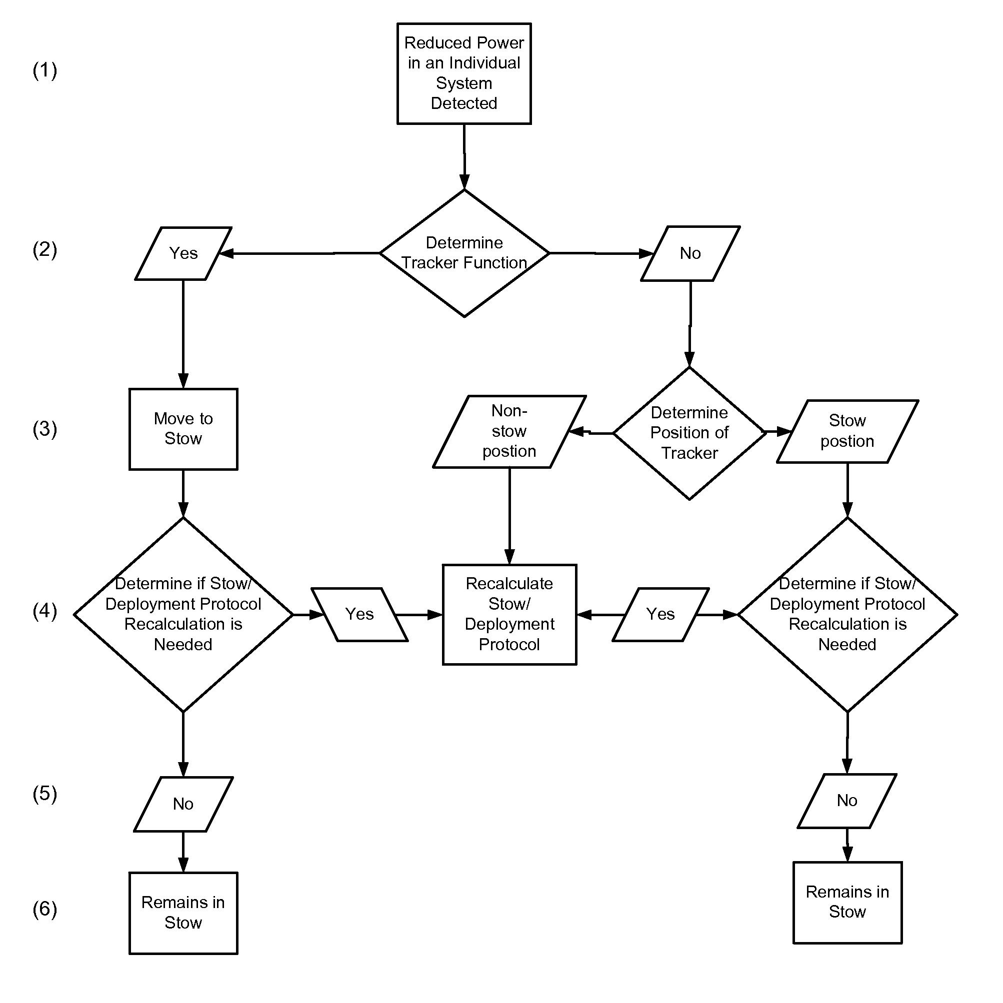
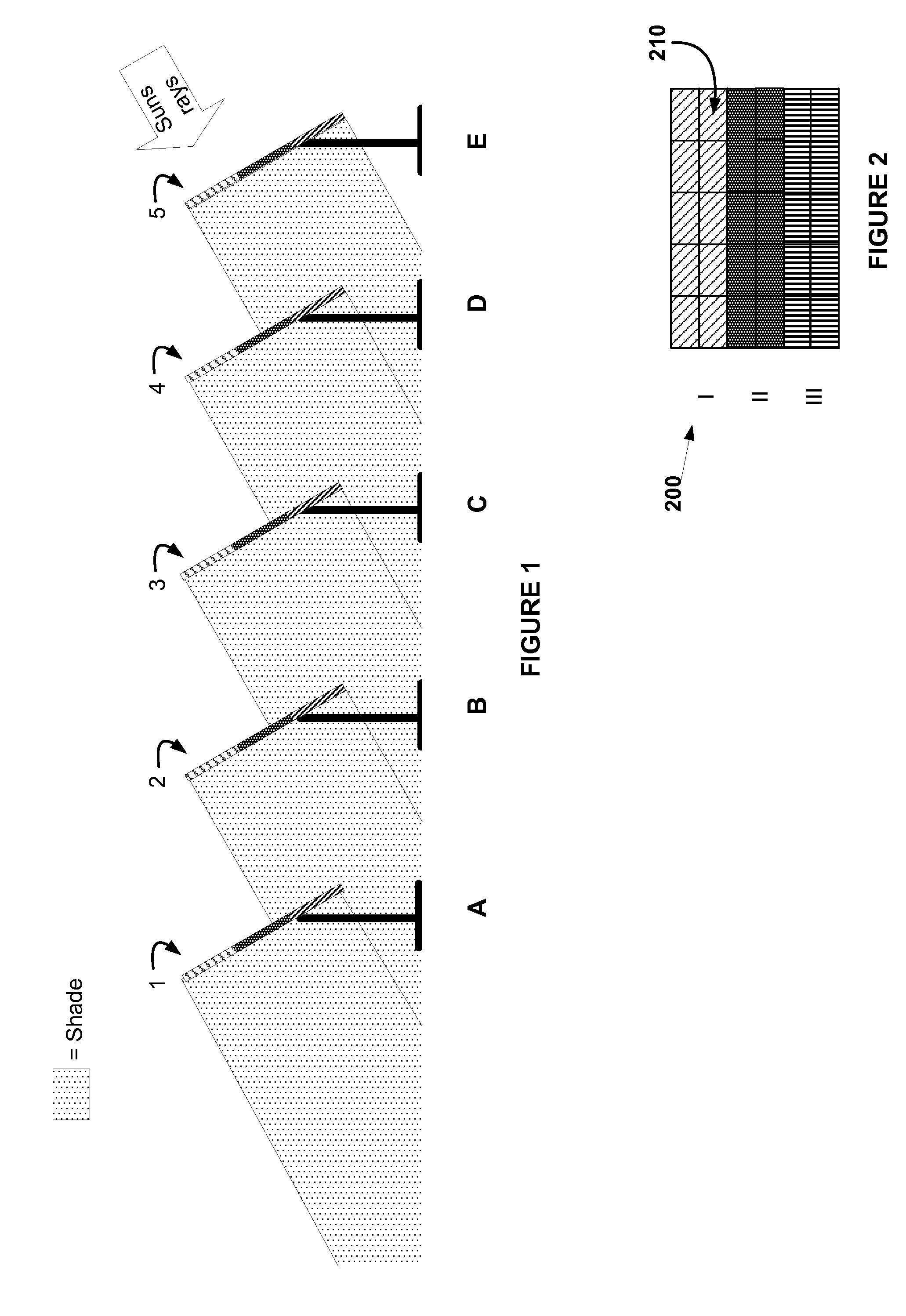
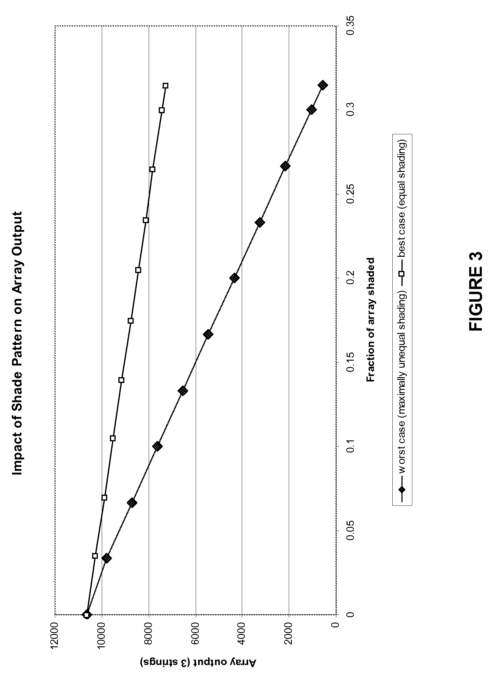
[0007]According to one embodiment of this invention the field level tracker controller may include an input means for entering the location and dimensions of individual solar energy systems in a field as well as the electronic arrangement of solar energy units in the system. The controller may also include a storage means for storing an algorithm that calculates an improved configuration of individual solar energy systems for maximum potential power (MPP) output of the sum of the solar energy systems based on the location and dimensions of each solar energy system in the field, the measured the power output generated by each solar energy systems in the field, the electronic arrangement of solar energy units in an array and the ephemeris equation for solar movement. In another embodiment, the field level tracker controller may orient a first portion of solar energy systems to provide a minimum shade pattern on a second portion of solar energy systems in order to provide for maximum potential power output of the sum of solar energy systems in a field. The minimum shade pattern on the systems in a field may be calculated by an algorithm using the ephemeris equation, location and dimensions of individual solar energy systems or other structures in the field to calculate the shade pattern generated by individual trackers or others structures. In a further embodiment the field level tracker controller may monitor the output of individual solar energy systems and calculate an improved set of positions where one or more solar energy trackers may be malfunctioning. The field level controller system offers the unique aspect of maximizing power output for a field of solar energy systems as a whole rather than on an individual system basis.

Problems solved by technology

This results in a sparse distribution of trackers in a field.
Consequently, performance in neighboring solar energy systems may be reduced.
Current tracker controllers do not account for elements in the landscape that may periodically block solar radiation, such other trackers, trees, buildings or inoperative trackers.
Furthermore, trackers designed to maximize power output at the array level can result in sub-optimal power generation of the field as a whole.

Method used


Image

  • Field Level Tracker Controller
  • Field Level Tracker Controller
  • Field Level Tracker Controller

Examples


Embodiment Construction

[0017]The present invention will now be described more fully herein with reference to the accompanying drawings. This invention may, however, be embodied in many different forms and should not be construed as limited to the embodiment set forth herein; rather, these embodiments are provided so that this disclosure will be thorough and complete and will fully convey the scope of the invention to those skilled the art. Like numbers refer to like elements throughout.

[0018]In one embodiment of this invention, a field level tracker controller may controllably position one or more individual solar energy systems in a field of solar energy systems. A solar energy system may include one or more arrays of units used for converting solar energy into useable electrical energy. The solar energy units in an array may be combined electrically in one or more strings. The solar energy units may be concentrated photovoltaic devices. The solar energy units may be flat panel solar energy devices. A so...


PUM


Abstract

The present invention is directed to an apparatus and method for improving the total power output from a field of solar energy systems. The invention provides a field level tracker controller which calculates an improved positioning of individual solar energy systems and communicates those configurations to trackers in the field. An algorithm stored in the controller calculates the improved configuration for the solar energy systems based on factors such as solar movement, shade patterns generated by surrounding structures, and measured output of the energy systems. Improved positioning may include individual energy systems being directed to a stowed position to maximize the power output of the field as a whole.

Description

RELATED APPLICATIONS[0001]This application is related to McDonald et al, U.S. patent application Ser. No. ______, entitled “Field Level Inverter Controller,” (Attorney Docket No. So1fP164 / SF-P184A) filed on even date herewith and hereby incorporated by reference.BACKGROUND OF THE INVENTION[0002]Solar energy systems are used to collect solar radiation and convert it into useable electrical energy. A system typically includes an array of solar energy units mounted on a tracker and a controller directing the tracker via a drive motor. Automated tracker controllers for solar energy systems are used to direct solar energy units to follow the path of the sun. The controller generally relies on the precise and accurate position of the tracker, a clock or timing mechanism and the ephemeris equation to calculate the relative direction of the solar radiation with respect to an array of solar energy units. Controllers typically control a single tracker that may support one or more arrays of so...

Claims


Application Information

Patent Timeline
IPC IPC(8): F24J2/38F24S50/20
CPCF24J2/38F24J2002/0084H02S20/00Y02E10/47Y02E10/50G01S3/7861F24S50/20F24S2020/16H02S10/00H02S50/00H02S20/32
Inventor MCDONALD, MARK
Owner SUMITOMO ELECTRIC IND LTD
Learn More