Solar energy concentrator and mounting method

a solar energy concentrator and mounting method technology, applied in the field of solar energy concentrator and mounting method, can solve the problems of difficult to achieve, difficult to synchronise and correct the optimum functioning of the solar modules, and expensive structures

Inactive Publication Date: 2010-08-26
ALEJO TREVIJANO JOSE JAVIER
View PDF10 Cites 68 Cited by
  • Summary
  • Abstract
  • Description
  • Claims
  • Application Information

AI Technical Summary

Benefits of technology

[0051]In this way, a perfect synchronisation is achieved in the movement of rolling and displacement towards one and the other side of the modules so that they can be oriented according to the position of the sun.
[0052]Another characteristic of the invention is that each general duct, which interconnects the balancing tanks, is linked to the ends of some rocker arms which are linked in their centres to some vertical posts, the free ends of those rocker arms being associated with a tensioning cable. In this way, a hor

Problems solved by technology

There currently exist different systems for energy generation by solar concentration, such as for example a system of multiple motorized mirrors which concentrate the heat in a high point or tower for heating up a fluid and generating steam for driving a turbine, parabolic Stirling concentrators, solar wind chimneys, parabolic cylindrical mirror concentrators, but they are all expensive with complex structures and require several years for installation in an average size solar plant.
Nevertheless, in practice this is difficult to achieve and from a beam of white light, which contains the entire range of colours, a cell only utilises a portion corresponding to the frequency of light to which the cell is most sensitive.
The drawback of this method is that the laminas themselves partially block off the passage of light.
The drawback of this technique is that the focal distance or point between the filter and the point of incidence of the light is very large, and a lot of space and volume is needed for mounting a module composed of a holographic filter and solar cells.
This design requires a lot of space and volume and, besides, the prisms do not decompose 100% of the light reflected off their fa

Method used


Image

  • Solar energy concentrator and mounting method
  • Solar energy concentrator and mounting method
  • Solar energy concentrator and mounting method

Examples


first embodiment

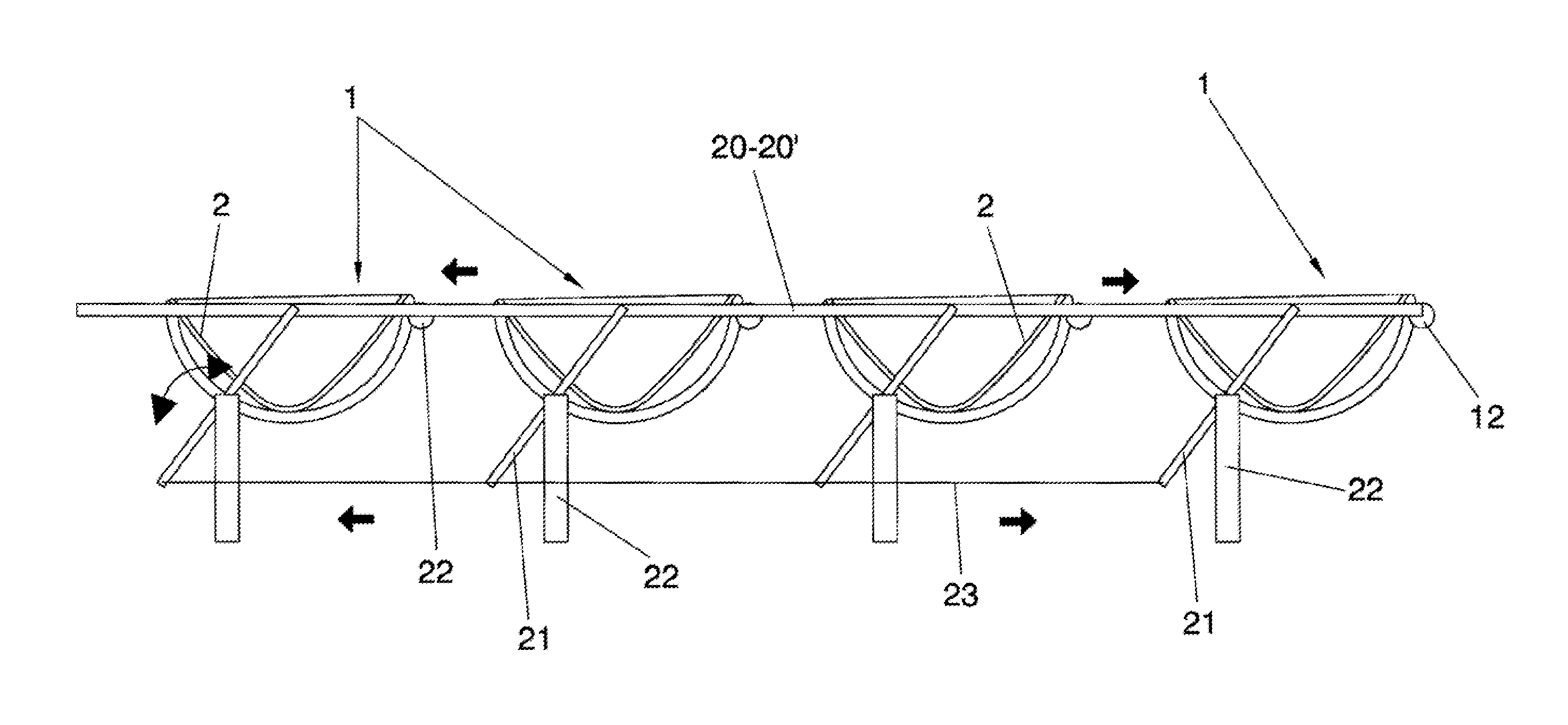
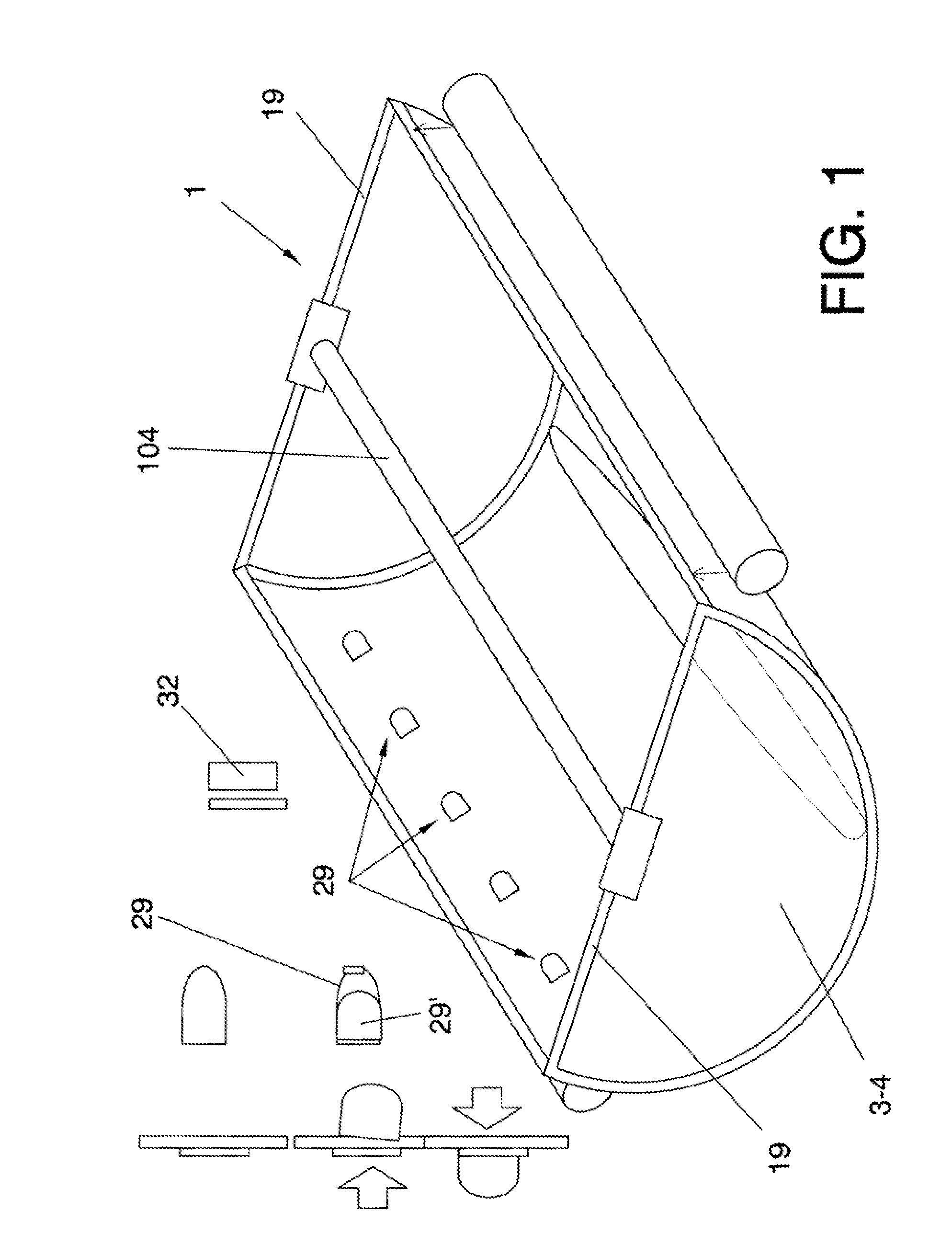
[0134]On the other hand, in a first embodiment, for positioning each module 1 or array of modules 1 in real time, provision has been made for two side tanks 12 which, depending on the relative variation among the weights of the material contained in those tanks 12, vary the orientation of the respective module 1, with the material passing from one tank to the other mechanically and / or electrically in order to balance and achieve each position of the module 1 depending on the light sensor or timer, with the material being transferred from one to another tank and vice versa, in accordance with the position of the sun.

[0135]The side tanks 12 can be hung in tilting fashion in the uppermost part of the sides of each module 1 along their length by means of some short chains or stays 13, or similar.

[0136]The material contained in those tanks 1 can be a liquid fluid that is transferred by means of a closed circuit from one tank to the other via lower zones with the aid of hydraulic equipmen...

second embodiment

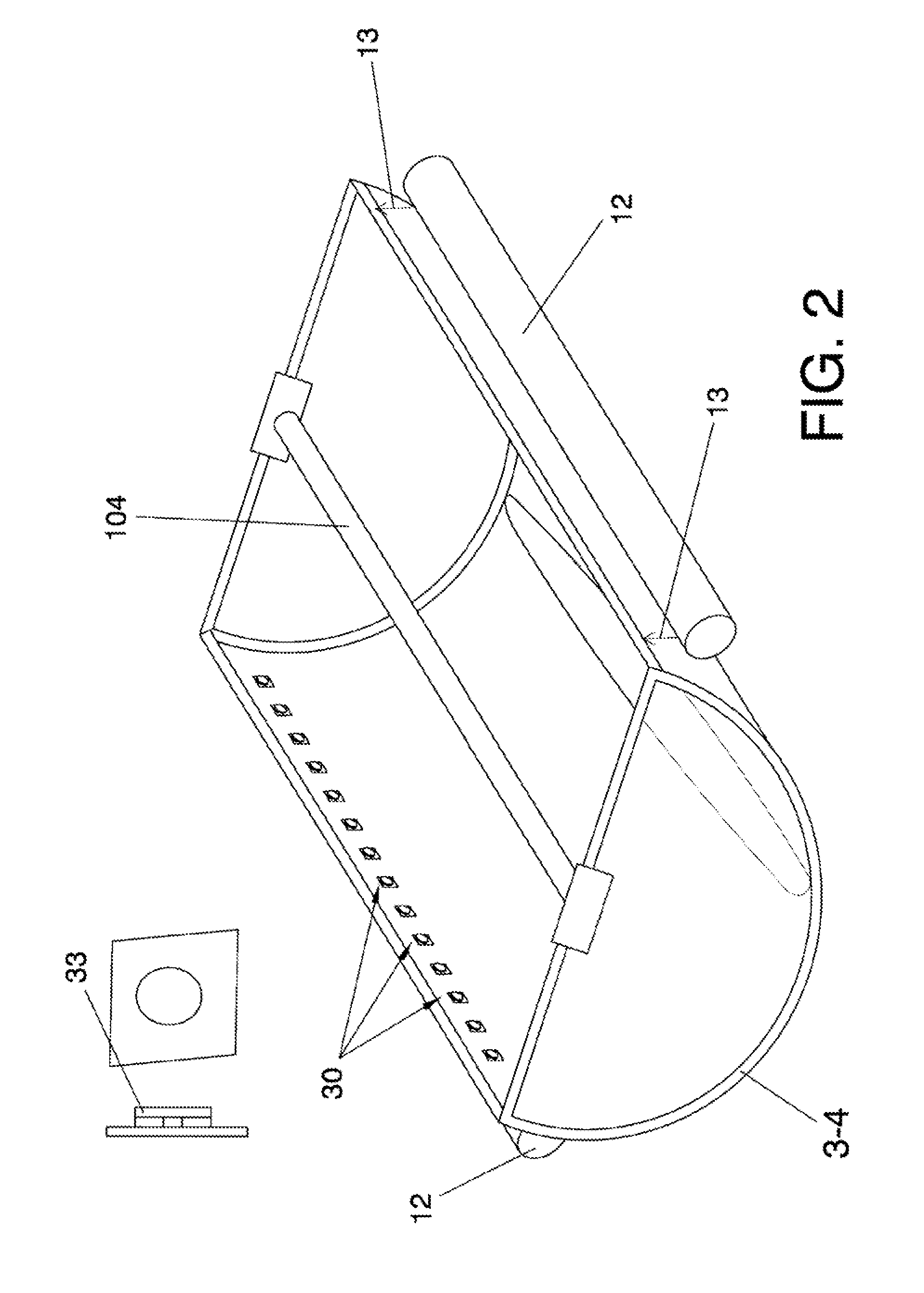
[0150]In a second embodiment shown in FIG. 2, provision has been made for some air passages 30 associated with some pieces 33 with their front face covered with mirror material in order not to lose any reflecting surface.

third embodiment

[0151]In a third embodiment, provision has been made for a succession of holes 31 made directly in the laminar mirror bodies 2.

[0152]When the modules 1 are of large dimensions, provision has been made for the incorporation of some lateral reinforcements 34 and a central one 35, all of them joined by means of a stay 36. The central reinforcement 35 is optional and is provided on a possible central collimator or other structure located in that zone for the reception of solar radiation.

[0153]As shown in FIG. 10, provision has been made for a cleaning system defined on the basis of a self-propelled vehicle 37 which runs along each module 1 via its lowest part, said vehicle 37 incorporating two large cleaning brushes 38 which lead to some pipes 39 supplying fluid with the appropriate cleaning products, the fluid being housed in a tank 40 of the vehicle 37. It includes a control circuit 41 and sensors 42, motor 43 and rechargeable battery 44 by means of a plug 45 which will be connected t...


PUM

PropertyMeasurementUnit
Frequencyaaaaaaaaaa
Frequencyaaaaaaaaaa
Pressureaaaaaaaaaa

Abstract

It includes at least one module with a concave reflecting mirror surface which concentrates the light radiation towards certain devices in order to then obtain electrical or other type of energy. It also includes means for orienting that mirror surface according to the position of the sun.
It is characterised in principle in that each module comprises a thin lightweight laminar body with an arched structure which incorporates the concave mirror surface, this laminar body being associated with certain stiffening supports which stabilise and stiffen that arched structure in order to maintain this shape, said structure being supported on some ground with the interposition of guide means by which the arched structure at least tilts towards one side or the other depending on the light sensor or timer which activates a device that positions each module in real time with the required orientation according to the position of the sun.

Description

OBJECT OF THE INVENTION[0001]As stated in the title of this descriptive specification, the present invention relates to a solar energy concentrator and mounting process.[0002]The solar energy concentrator is intended to concentrate light radiation from the sun with the aim of obtaining electrical energy or energy in the form of heat for heating fluids such as water. It is also intended to achieve other energy resources such as hydrogen and oxygen by means of a photolysis process or for use with systems which need light or heat from the sun for their generation and / or also for purification or desalination of water.[0003]The concentrator in general comprises high efficiency modules possessing a light and simple structure, requiring a low cost for their installation, furthermore requiring a low cost per each specific module.[0004]Moreover, the mounting process is substantially simple and rapid, being able to be carried out directly on the ground or with the interposition of some guides...

Claims


Application Information

Patent Timeline
IPC IPC(8): F24J2/38B23P15/26F24J2/02F24J2/08F24J2/24F24J2/10F24S10/70F24S20/30F24S23/30F24S23/70F24S23/74F24S50/20
CPCF24J2/085Y10T29/53113F24J2/32F24J2/461F24J2/4638F24J2/541F24J2002/5281F24J2002/5441F24J2002/5458F24J2002/5462F24J2002/5468F24J2002/5493Y02E10/43Y02E10/44Y02E10/45Y02E10/46Y02E10/47Y02E10/52H02S20/00H01L31/0543H01L31/0547F24J2/14F24S10/95F24S23/31F24S23/74F24S30/425F24S40/20F24S40/85F24S2025/014F24S2030/115F24S2030/133F24S2030/134F24S2030/136F24S2030/18H02S20/10H02S20/30H02S40/22Y02E10/40
Inventor ALEJO TREVIJANO, JOSE JAVIER
Owner ALEJO TREVIJANO JOSE JAVIER
Why Eureka
Try Eureka