Shut Off Protection For Hot Water Heater

a technology for shutting off protection and hot water heaters, applied in the field of water heaters, can solve the problems of valve failure, leakage of water, and damage to the structure and contents, and achieve the effect of preventing further water leakage and damag

Inactive Publication Date: 2010-08-26
FIMA GIOVANNI
View PDF9 Cites 46 Cited by
  • Summary
  • Abstract
  • Description
  • Claims
  • Application Information

AI Technical Summary

Benefits of technology

[0007]The inventive subject matter provides systems and methods that seek to shut down water flow to a water heater of a residential, commercial, or other structure, when a leak is detected. Contemplated water heaters include storage water heaters, tankless or instantaneous water heaters, as well as all other commercially available water heaters. Preferred systems have first and second valves, as well as first and second valve actuators that operate the respective first and second valves. With first and second valves, the systems can advantageously stop the flow of water into and out of the water heater when a leak is detected, and thereby prevent further water leakage and damage. Preferred systems also have first and second sensors that measure a flow of water into and out of the water heater, respectively. A controller can advantageously receive a signal from each of the sensors, and communicates with each of the valve actuators.
[0013]Others sensors could also be used with the system including for example, smoke detectors and earthquake sensors. Such sensors could be advantageous as they allow the water heater to be shut down in the event of a dangerous condition such as a fire or earthquake, and might thereby prevent possible water damage or explosions.
[0017]Preferably, the controller is user pluggable into a power grid. It is also contemplated that the controller could be hard-wired to the power grid or other power source including for example, a battery or solar panel. In addition, the controller could comprise electronics to allow it to communicate over a power line, such as by an IP over power line connection, the use of X10 modules, or any other commercially available connection. This is advantageous as it allows the controller to be user-installed, and provide power to the sensors and valve actuators. In addition, the controller could thereby communicate with a remote monitor over the power line without the need for additional wiring.
[0020]The controller could be further programmed to interrupt at least one of a flow of gas and electricity to the water heater when the controller communicates with the first and second valve actuators to shut the first and second valves. This is advantageous as it helps prevent possible fires, explosions, or other problems that could occur when the water flow into and out of the water heater is stopped. The controller or thermocouple could interrupt the flow of gas by communicating with an optional third valve actuator to shut a third valve and thereby prevent gas flow to the water heater. It is also contemplated that the controller could interrupt electricity to the water heater through the use of a built-in switch or by communicating with an external switch to stop electricity to the water heater.

Problems solved by technology

Hot water heaters often develop leaks over time, which if they continue undetected can cause significant damage to a structure and its contents.
Since water heaters typically lack any ability to detect leaks, such leaks often go unnoticed until significant damage occurs.
Furthermore, while water heaters generally have a blow-out valve to prevent explosions, such valves tend to build-up lime and other mineral deposits over time, which can cause the valves to fail.
One problem with the Akkala solution is that the sensors are typically placed underneath water heaters, which are generally located in an outdoor or semi-outdoor location and thus often corrode and malfunction.
In addition, sensors positioned underneath a water heater often falsely trigger, such as from a small amount of water that might inadvertently come into contact with the sensors.
Such sensors also fail to adequately monitor for leaks in tankless water heaters, as such water heaters typically are mounted to a wall, rather than a floor.
However, one problem with the Hirano system is that it fails to automatically shut down the system when a leak is detected.
In addition, the system fails to be user-installable, and instead requires trained technicians for installation.

Method used


Image

  • Shut Off Protection For Hot Water Heater
  • Shut Off Protection For Hot Water Heater
  • Shut Off Protection For Hot Water Heater

Examples


Embodiment Construction

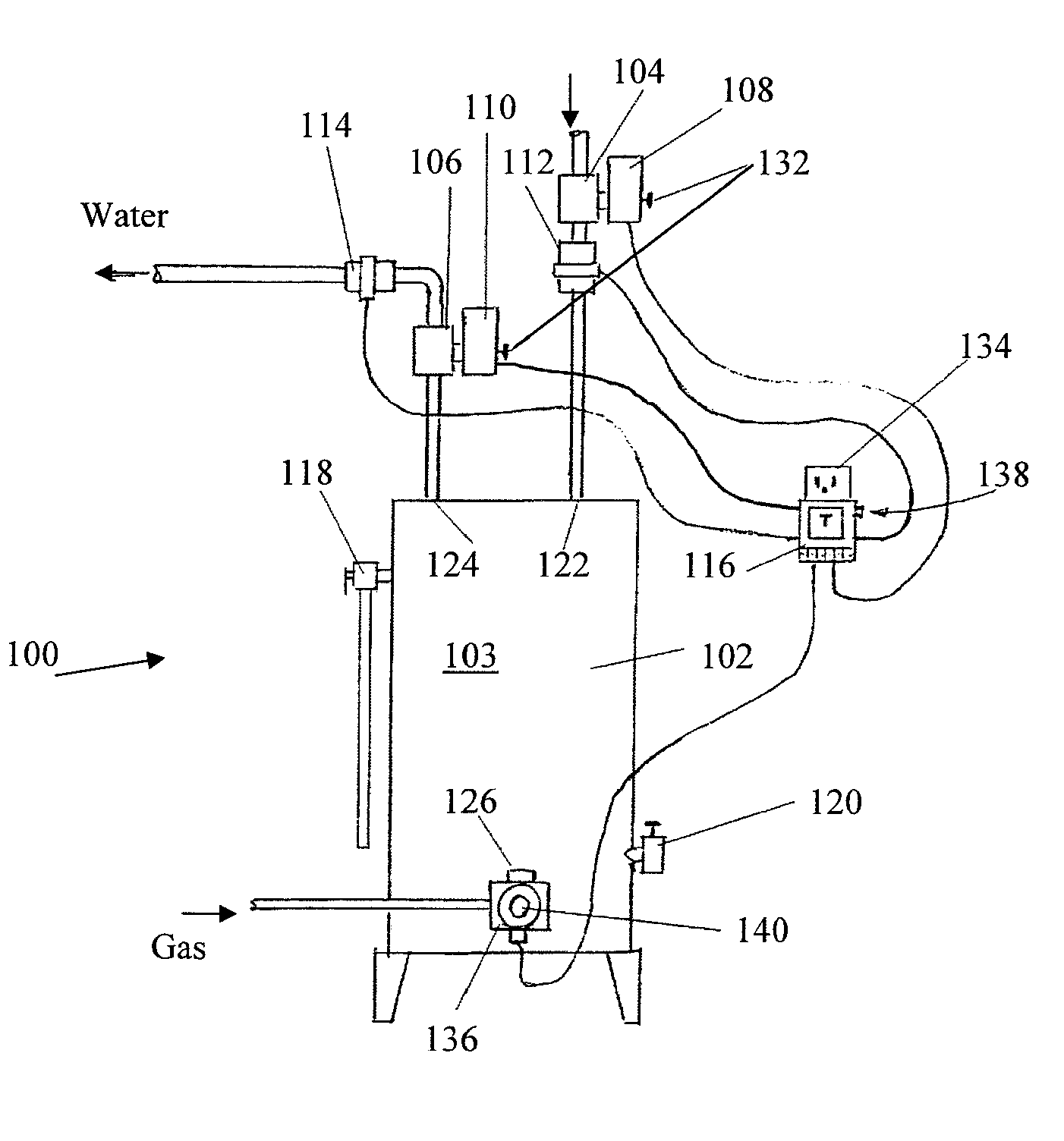
[0028]In FIG. 1, system 100 is designed to shut off water flow to a water heater 102 upon detection of a leak. System 100 includes first 104 and second valves 106, first 108 and second valve actuators 110, first 112 and second sensors 114, and a controller 116.

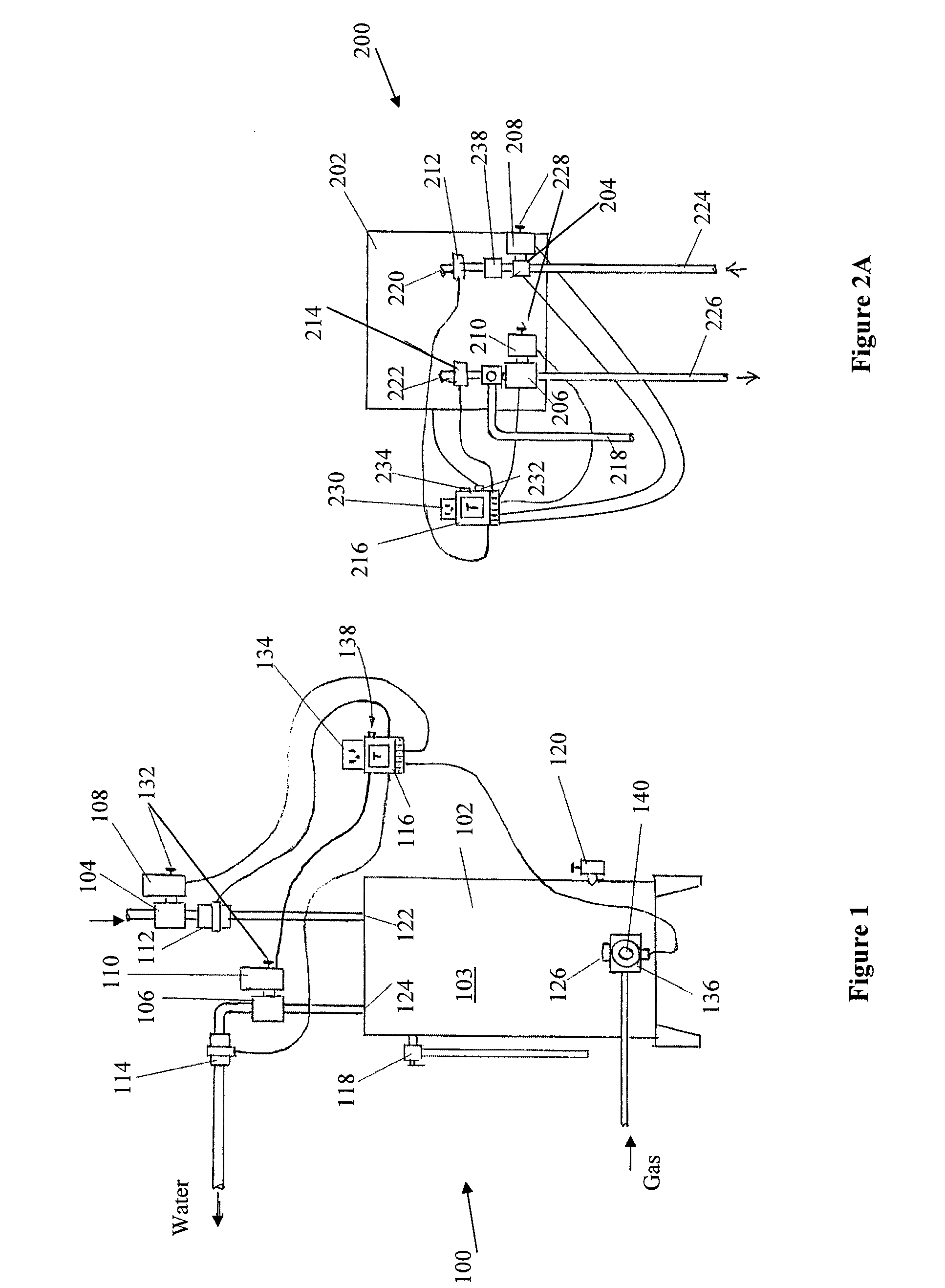
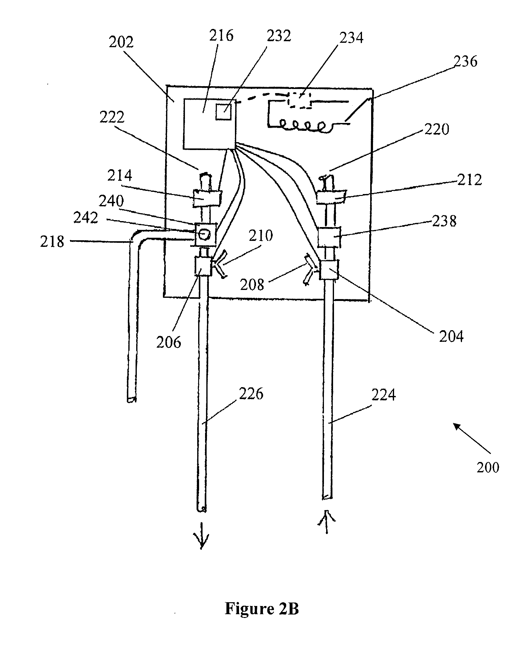
[0029]Water heater 102 has a storage tank 103 for storing hot water. However, system 100 is contemplated to work with any commercially available water heater including for example, tankless water heaters shown in FIGS. 2A-2B, as well as other water heaters and boilers. Water heater 102 includes blowout valve 118 and drain pipe 120. Preferably, blowout valve 118 comprises a check valve that opens at a defined pressure threshold. Water heater 102 also includes a fluid inlet 122 and a fluid outlet 124. Water heater 102 further includes gas inlet 126, though it is contemplated that other sources of energy could be used including for example, oil and electricity.

[0030]First 104 and second valves 106 are disposed on an inlet pipe or...


PUM

PropertyMeasurementUnit
temperatureaaaaaaaaaa
pressureaaaaaaaaaa

Abstract

A system that shuts down water flow to a water heater of a residence or commercial building upon detecting a leak that includes first and second valves, and first and second valve actuators that operate to control the first and second valves, respectively. Preferred systems also include first and second sensors that measure the flow of water into and out from water heaters, respectively. Preferred systems further include controllers that receive signals from each of the first and second sensors. Such controllers controllably communicate with each of the first and second valve actuators to close the first and second valves, respectively, when a flow difference is detected that is greater than a predetermined threshold.

Description

FIELD OF THE INVENTION[0001]The field of the invention is water heaters.BACKGROUND[0002]Hot water heaters often develop leaks over time, which if they continue undetected can cause significant damage to a structure and its contents. Since water heaters typically lack any ability to detect leaks, such leaks often go unnoticed until significant damage occurs. Furthermore, while water heaters generally have a blow-out valve to prevent explosions, such valves tend to build-up lime and other mineral deposits over time, which can cause the valves to fail.[0003]It is known to place sensors beneath water heaters to detect leaks. For example, U.S. Patent Appl. No. 2007 / 0261241 to Akkala, et al. discusses the use of such a sensor, which closes a valve to the water heater when the sensor detects water. One problem with the Akkala solution is that the sensors are typically placed underneath water heaters, which are generally located in an outdoor or semi-outdoor location and thus often corrode ...

Claims


Application Information

Patent Timeline
Patent Type & Authority Applications(United States)
IPC IPC(8): G05D16/00B23P19/04
CPCF24H9/2007Y10T29/53G01M3/2807Y10T137/2708Y10T137/2703F24H15/136F24H15/238F24H15/242F24H15/36F24H15/395F24H15/37F24H15/335F24H15/31F24H15/223F24H15/20F24H15/45F24H15/12F24H15/215
Inventor FIMA, GIOVANNI
Owner FIMA GIOVANNI
Why Eureka
Try Eureka