
Pneumatic Tire

a technology of pneumatic tires and cylinders, which is applied in the direction of vehicle components, transportation and packaging, non-skid devices, etc., can solve the problems of reducing wet performance (a traveling performance on a wet road surface), affecting the performance of tires, and cracking of groove bottoms, so as to prevent the peak of noise level from being generated, reduce car exterior noise, and inhibit the frequency of pipe resonance noise

Inactive Publication Date: 2010-08-26
TOYO TIRE & RUBBER CO LTD
View PDF9 Cites 8 Cited by
  • Summary
  • Abstract
  • Description
  • Claims
  • Application Information

AI Technical Summary

Benefits of technology

[0010]The present invention is made in view of the above-mentioned circumstances, and an object of the present invention is to provide a pneumatic tire which can improve a discharging characteristic of a stone getting into a main groove, can reduce a car exterior noise, and which is also excellent in a wet performance.Means for Solving the Problems
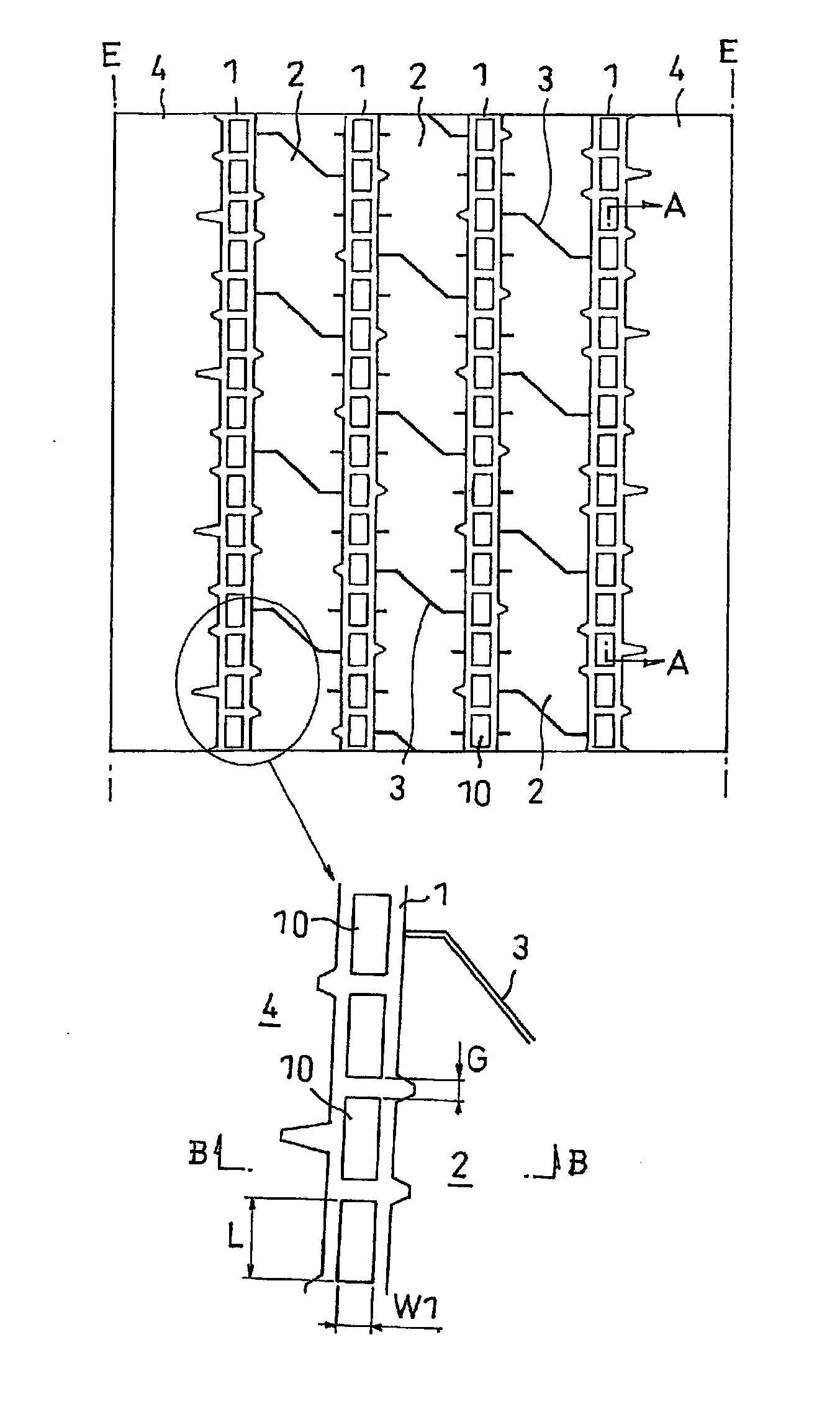
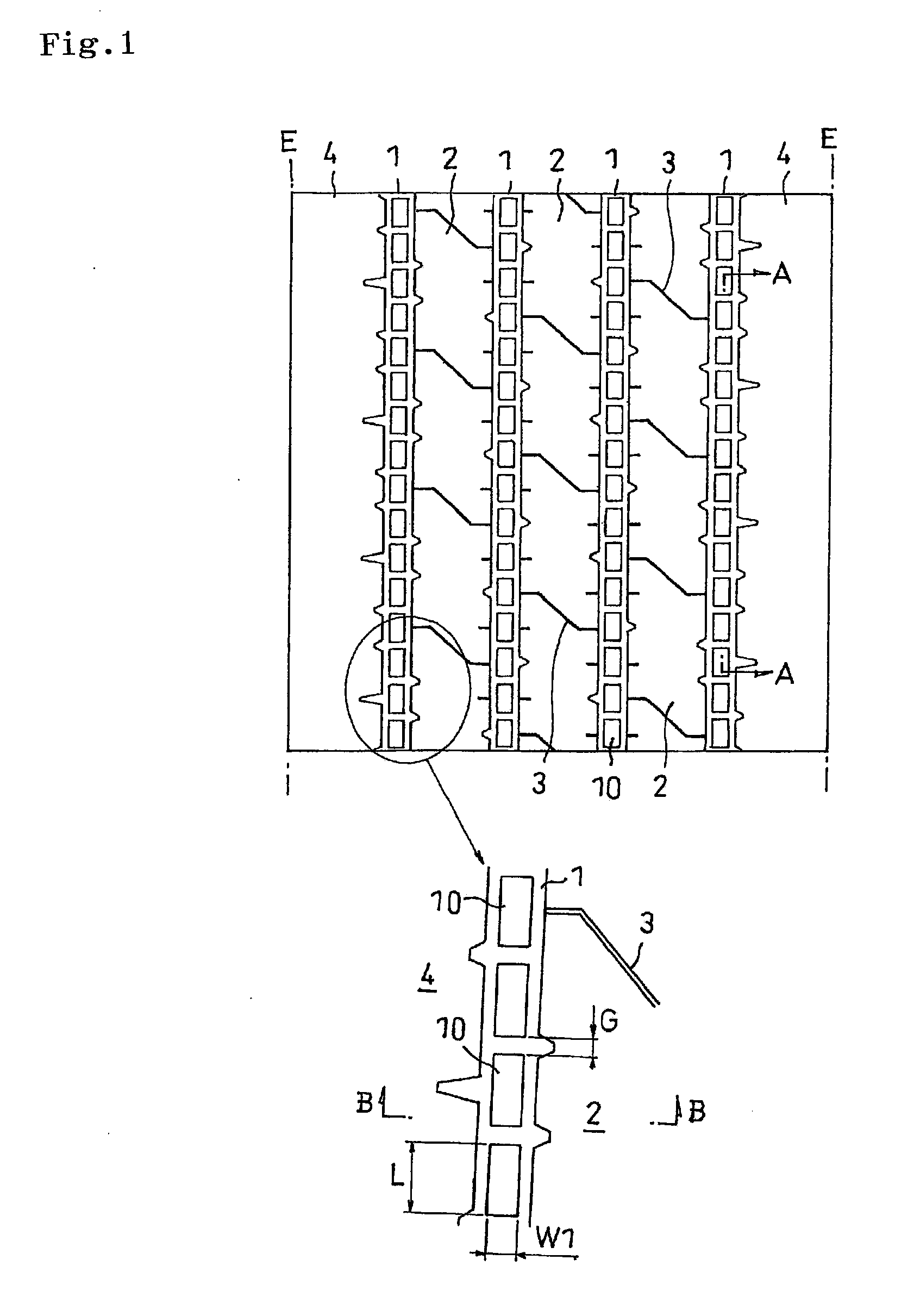
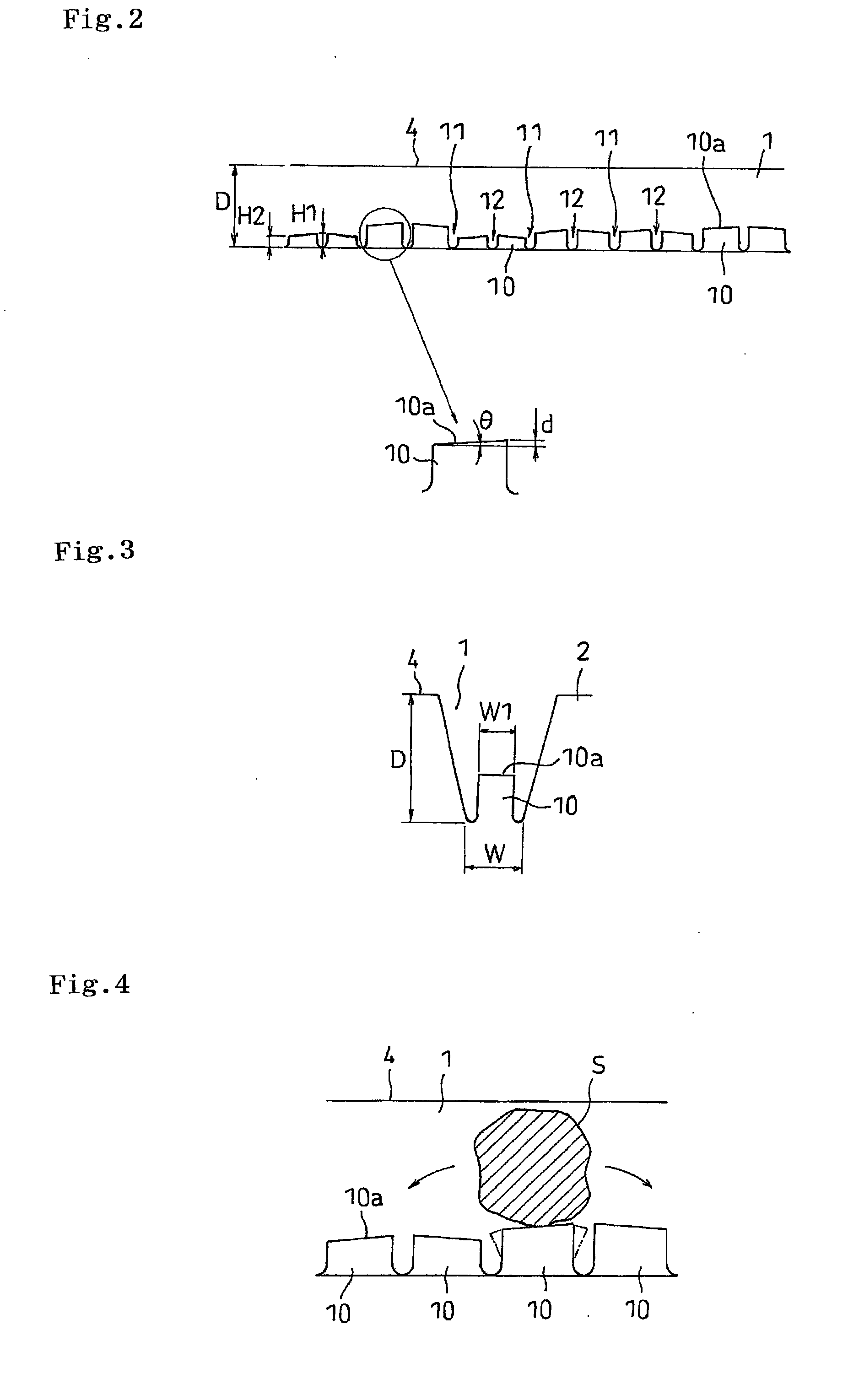
[0012]In accordance with the present invention, the plurality of projections having the different heights are provided in the grove bottom of the main groove such that the outer peripheral surface is inclined so as to repeat the trough portions depressed to the inner side in the tire diametrical direction and the peak portions protruding to the outer side in the tire diametrical direction along the tire circumferential direction, the stone getting into the main groove is hard to stay at the specific position. Further, since each of the projections which are varied in height can move the stone in the main groove via the inclined outer peripheral surface when elastically deforming along the tire circumferential direction, it is possible to discharge the stone out of the main groove by the centrifugal force arising in connection with the tire rolling motion in cooperation with the effect that the stone is hard to stay as mentioned above.
[0013]Further, in accordance with the present invention, since the projections having the different heights are provided in the groove bottom of the main groove along the tire circumferential direction, it is possible to intermittently or continuously change a frequency band of a pipe resonance noise by varying the volumetric capacity of the closed space formed by the main groove and the road surface at the time of grounding. Accordingly, it is possible to inhibit the frequency of the pipe resonance noise from coinciding with the frequency generating a pitch peak noise which is defined by a pattern pitch of the tread surface and a traveling speed, and it is possible to prevent the peak of the noise level from being generated so as to reduce the car exterior noise. Further, a reducing margin of the groove volumetric capacity is less compared with the case where the projection continuously extending in the tire circumferential direction is provided, and it is possible to satisfactorily secure the wet performance.
[0014]In accordance with the present invention, the trough portion can be formed by inclining the outer peripheral surfaces of the projections which are adjacent to each other in the tire circumferential direction to the inner side in the tire diametrical direction toward the direction coming close to each other. With such a structure, in the case where the stone gets into the trough portion, it is possible to move the stone by deformation of the projections on both sides configuring the trough portion, and it is possible to achieve a more excellent stone discharging performance.
[0015]In the above structure, it is preferable that a maximum height of the projection in the peak portion is between 10 and 35% a depth of the main groove from the groove bottom of the main groove, and a minimum height of the projection in the trough portion is equal to or more than 2.5 mm from the groove bottom of the main groove. Since the maximum height of the projection in the peak portion is between 10 and 35% the depth of the main groove, it is possible to properly secure the rigidity of the projection, and it is possible to satisfactorily secure the wet performance by inhibiting the groove volumetric capacity from being reduced, as well as it is possible to inhibit the stone from being held between the projection and the side wall of the main groove. Further, since the minimum height of the projection in the trough portion is equal to or more than 2.5 mm, it is possible to effectively prevent the stone from reaching the groove bottom so as to more suitably prevent the tire from being damaged.
[0016]In the above structure, it is preferable that a part or all of the trough portions are depressed in a V-shaped form to the inner side in the tire diametrical direction, and a part or all of the peak portions protrude in an inverted V-shaped form to the outer side in the tire diametrical direction. With such a structure, since the trough portion is depressed in the V-shaped form to the inner side in the tire diametrical direction, it is possible to effectively prevent the stone from staying within the main groove, thereby the stone is easily moved along the tire circumferential direction, and a more excellent stone discharging performance can be achieved. Further, since the peak portion protrudes in the inverse V-shaped form to the outer side in the tire diametrical direction, the wall surface in the tire circumferential direction of one of the projections forming the peak portion does not protrude largely from the other, and it is possible to prevent the deficit or the like from being generated by the stone contact.

Problems solved by technology

Further, if the tire rolls in a state in which such stone holding has occurred, the wedged stone presses a groove bottom, or a force intending to push and expand the main groove is repeatedly applied, thereby causing a damage such as a groove bottom crack.
However, in the above-mentioned tire, it is possible to somewhat inhibit the stone holding from being generated, however, there is a risk that the stone getting into the main groove stays at a low position of the projection, and there is fear that a repeated grounding of this portion damages the tire.
On the contrary, it is possible to consider setting each of the projections a little higher, however, in that case, there is generated a problem that the stone is held between the projection having the low rigidity and the side wall of the main groove, and a wet performance (a traveling performance on a wet road surface) is lowered due to a reduced volumetric capacity of the groove.
However, since the concave portion and the convex portion are continuously provided, it is hard to give a great change in rigidity even by varying the heights, and it is considered that the discharging characteristic of the stone is not greatly improved.
Further, there is generated a problem that the wet performance is lowered due to a reduced volumetric capacity of the groove.

Method used


Image

  • Pneumatic Tire
  • Pneumatic Tire
  • Pneumatic Tire

Examples


example

[0059]As an example, a pneumatic tire in which the height of the projection is variously different and the outer peripheral surface of the projection is inclined in such a manner that the trough portions and the peak portions are repeated, in the tread patterns shown in FIGS. 1 and 2, was used. The tire circumferential length L of the projection and the gap G of the projection are the same as the comparative example 1, a range of a height H1 of the projection is between 3.0 and 4.8 mm, a height H2 is equal to or more than 2.5 mm, a height difference d between a highest portion and a lowest portion of the projection is equal to or more than 0.5 mm, and an angle θ of inclination of the outer peripheral surface of the projection is equal to or less than 20 degrees. Results of the evaluation are shown in Table 1.

TABLE 1ComparativeComparativeComparativeexample 1example 2example 3ExampleStone8663dischargingperformanceNoise87.482.179.781.5characteristic

[0060]From Table 1, it is known that ...


PUM


Abstract

A pneumatic tire has a main groove extending along a tire circumferential direction in a tread surface. A plurality of projections having different heights are provided in a groove bottom of the main groove in such a manner that an outer peripheral surface is inclined so as to repeat trough portions depressed to an inner side in a tire diametrical direction and peak portions protruding to an outer side in the tire diametrical direction along the tire circumferential direction.

Description

TECHNICAL FIELD[0001]The present invention relates to a pneumatic tire provided with a main groove extending along a tire circumferential direction in a tread surface, in which a discharging performance of a stone that gets into the main groove can be improved.BACKGROUND ART[0002]When traveling on a gravel road or the like which is not leveled, a so-called stone holding in which a stone on the road is wedged between main grooves of a tread surface in a tire may be generated. Further, if the tire rolls in a state in which such stone holding has occurred, the wedged stone presses a groove bottom, or a force intending to push and expand the main groove is repeatedly applied, thereby causing a damage such as a groove bottom crack.[0003]Accordingly, a projection has been conventionally provided in the groove bottom of the main groove so as to prevent the stone holding. For example, the following Patent Documents 1 and 2 describe a pneumatic tire in which a plurality of projections are pr...

Claims


Application Information

Patent Timeline
IPC IPC(8): B60C11/117
CPCB60C11/047B60C11/042
Inventor KAJI, SHINICHI
Owner TOYO TIRE & RUBBER CO LTD
Learn More