

Light-emitting device and method of manufacturing the same
Inactive Publication Date: 2010-08-26
SONY CORP
View PDF21 Cites 60 Cited by
- Summary
- Abstract
- Description
- Claims
- Application Information
AI Technical Summary
Benefits of technology
[0019]In the method of manufacturing a light-emitting device according to the embodiment of the invention, the whole module is inclined at the time of bonding the thermal conductive member, so electric power is reliably supplied to the light-emitting element on a supporting base (the first supporting base), and heat dissipation is secured.
[0020]Other and further objects, features and advantages of the invention will appear more fully from the following description.
Problems solved by technology
However, the height of the first light-emitting element are largely different from the heights of the bumps, so it is technically difficult to firmly bond the second light-emitting element to both of the first light-emitting element and the bumps.
However, also in the method, as in the above-described case, the height of the first light-emitting element is largely different from the heights of the bumps, so it is technically difficult to firmly bond the second light-emitting element to both of the first light-emitting element and the bumps.
In the case where the second light-emitting element is not firmly bonded to the first light-emitting element or the bumps, there is an issue that it is difficult to supply electric power to the second light-emitting element.
Moreover, even if the second light-emitting element is bonded to the first light-emitting element and the bumps, thereby to allow electric power to be supplied to the second light-emitting element, there is an issue that heat generated in the second light-emitting element is not sufficiently conducted to the supporting base.
Method used
View moreImage
Smart ImageViewing Examples

Examples
first embodiment (
1. First Embodiment (including two light-emitting elements, and using a ribbon for a thermal conductive member)
second embodiment (
2. Second Embodiment (including two light-emitting elements, and using a lead frame for the thermal conductive member)
third embodiment (
3. Third Embodiment (including one light-emitting element, and using a ribbon or a lead frame for the thermal conductive member)
4. Modifications
Login to View More PUM
 Abstract
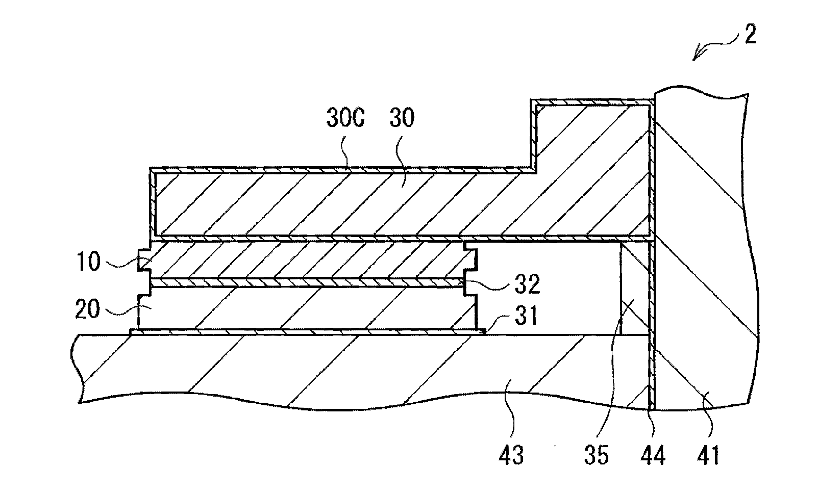
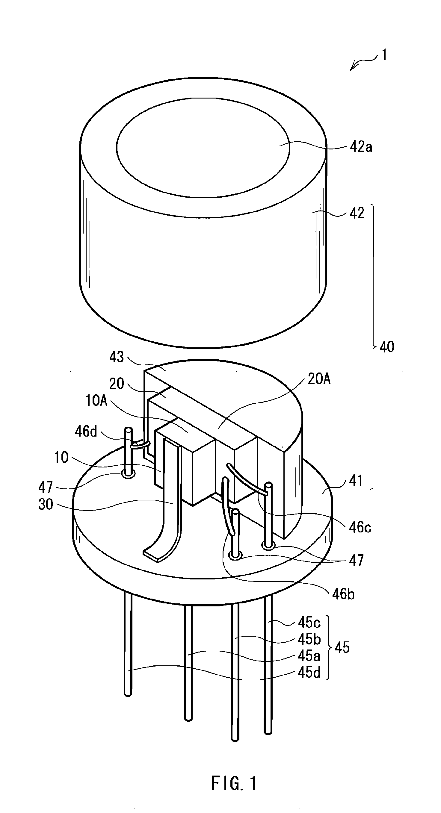
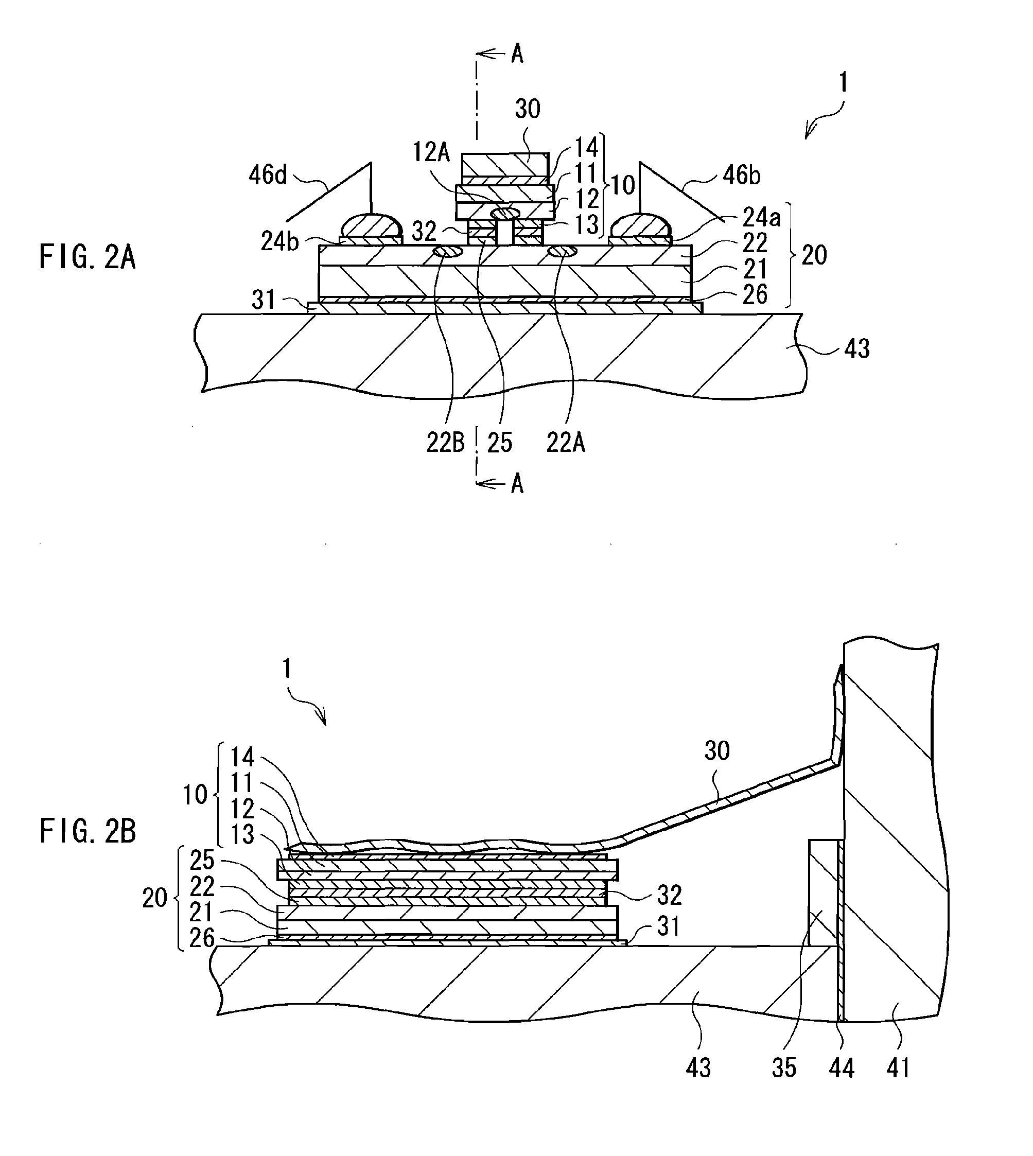
A light-emitting device reliably supplying electric power to a light-emitting element on a supporting base and securing heat dissipation, and a method of manufacturing the light-emitting device are provided. A light-emitting device includes: a light-emitting element arranged on a first supporting base; a package covering the first supporting base and the light-emitting element therewith, and supporting the first supporting base; and a thermal conductive member having ends which are bonded to the light-emitting element and the package, respectively, so as to also have a wiring function.
Description
BACKGROUND OF THE INVENTION[0001]1. Field of the Invention[0002]The present invention relates to a package-type light-emitting device including a light-emitting element contained in a package, and a method of manufacturing the light-emitting device.[0003]2. Description of the Related Art[0004]In recent year, in the field of semiconductor lasers, multiwavelength lasers including a plurality of light-emitting sections with different emission wavelengths on a common substrate (or a common base) have been actively developed. The multiwavelength laser is used as, for example, a light source for an optical disk device.[0005]In such an optical disk device, 700-nm-band laser light is used to replay a CD (a Compact Disk), and to record and reproduce data to / from a recordable optical disk such as a CD-R (a CD Recordable), a CD-RW (a CD Rewritable) or an MD (a Mini Disk). Moreover, 600-nm-band laser light is used to record and reproduce data to / from a DVD (a Digital Versatile Disk). When the m...
Claims
Login to View More Application Information
Patent Timeline
 IPC IPC(8): H01L33/00
CPCH01L23/055H01S3/0405H01L2224/48463H01L2224/48472H01L2924/01013H01L2924/01029H01L2924/01033H01L2924/01078H01L2924/01079H01L2924/01082H01L2924/10329H01L2924/10336H01L2924/10349H01L2924/30105H01L2924/3025H01S5/02212H01S5/0224H01S5/02264H01S5/02272H01S5/02276H01S5/02476H01S5/4043H01S5/4087H01L24/34H01L2924/01074H01L2924/01005H01L2924/01006H01L2924/01019H01L2924/01023H01L2924/00014H01L2924/12043H01L2224/37144H01L2224/371H01L2224/37124H01L2224/37147H01L2224/3754H01L24/37H01S5/02365H01S5/0234H01S5/0237H01S5/02345H01L2924/00H01L2224/73221
InventorFUKASAWA, HIROYUKINISHIDA, HIROSHI
OwnerSONY CORP