Heat sink base for LEDS

a technology of leds and sinks, applied in the field of light-emitting diodes, can solve the problems of reducing the efficiency of leds, generating color shifts, and producing more heat, and achieve the effects of enhancing heat dissipation, enhancing heat dissipation, and operating more efficiently

Active Publication Date: 2010-08-26
BRIDGELUX INC
View PDF26 Cites 18 Cited by
  • Summary
  • Abstract
  • Description
  • Claims
  • Application Information

AI Technical Summary

Benefits of technology

[0011]By providing enhanced heat dissipation from the LED dice, more current can be used so as to provide brighter LEDs that are suitable for use in such applications as flashlights, displays, and general lighting. Further, by providing enhanced heat dissipation for the LED dice, phosphors can be maintained at a lower temperature, such that the phosphors operate more efficiently. When phosphors operate more efficiently, desired colors can be provided thereby more reliably.

Problems solved by technology

However, brighter LEDs require more current and more current results in the production of more heat.
Heat reduces the efficiency of LEDs and undesirable generates color shifts.
Thus, although contemporary LEDs have proven generally suitable for some purposes, they possess inherent deficiencies which detract from their overall effectiveness and desirability.

Method used


Image

  • Heat sink base for LEDS
  • Heat sink base for LEDS
  • Heat sink base for LEDS

Examples


Embodiment Construction

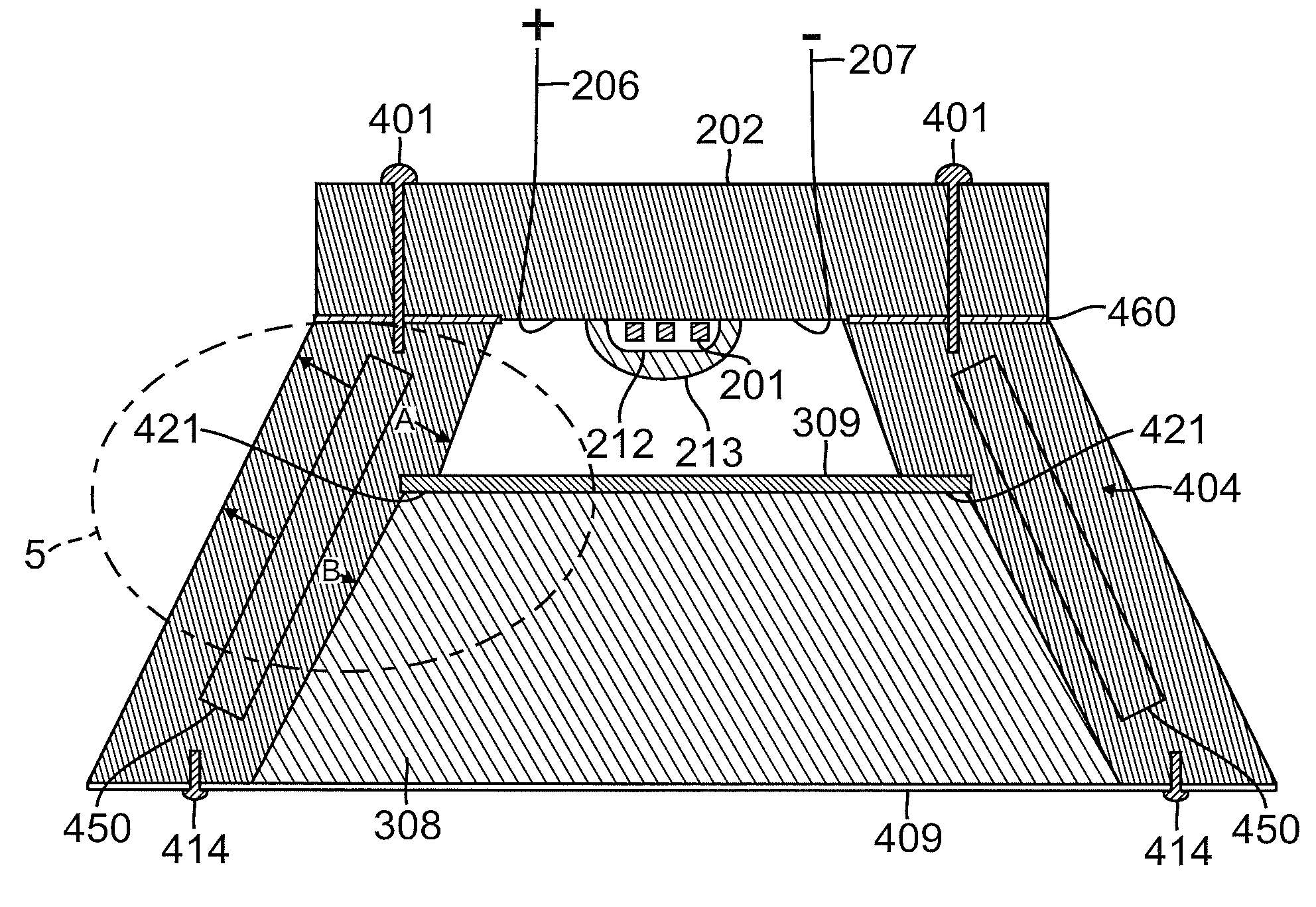
[0021]Methods and systems for enhancing the optical performance of a LED by reducing the temperature Tj of a junction or active area of the LED and / or by reducing the temperature of one or more phosphors of the LED are disclosed.

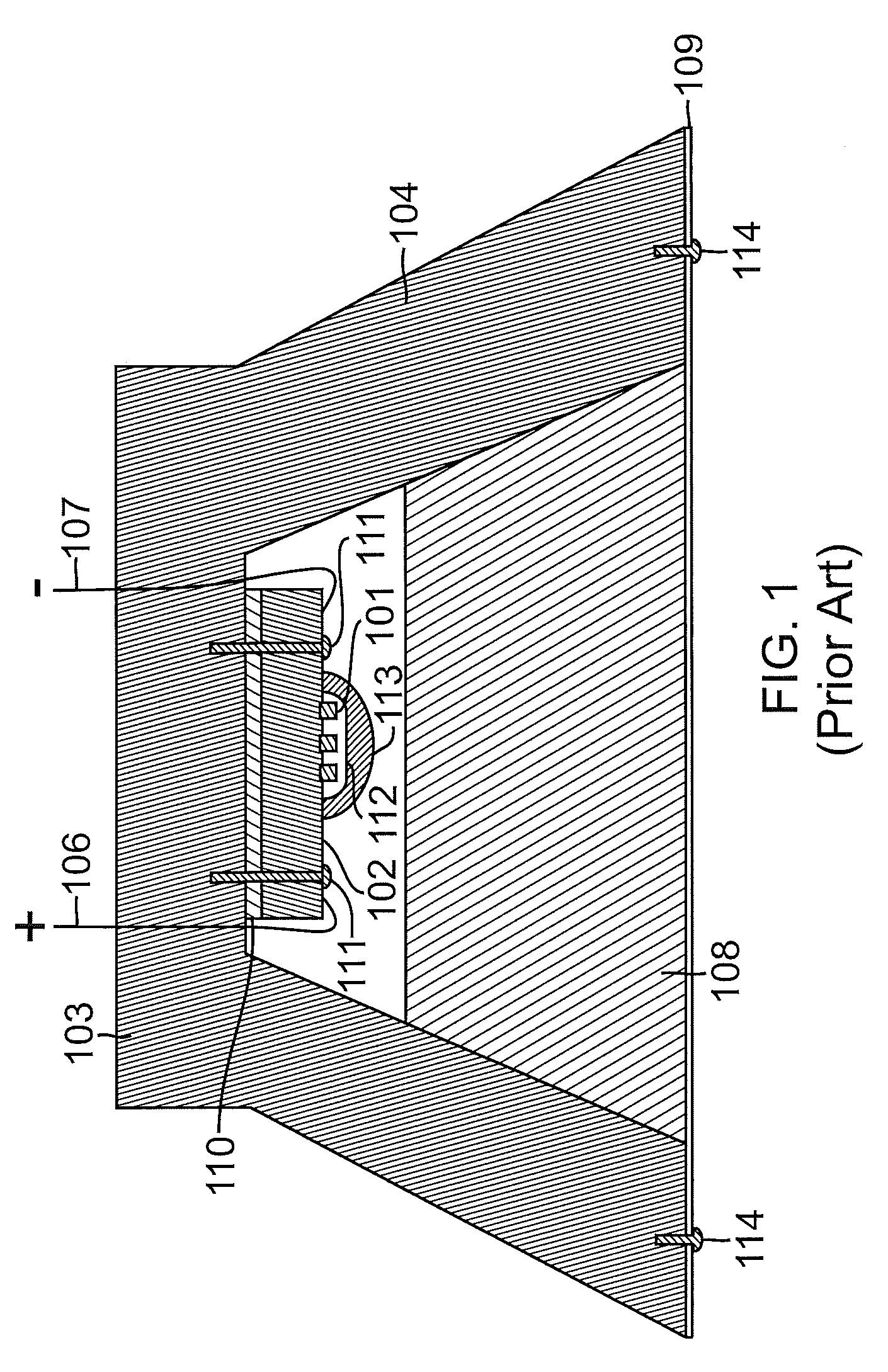
[0022]As discussed above, the heat produced by current flow through a light emitting diode (LED) can be accommodated, so as to facilitate the use of the higher currents that are required in order to provide brighter LEDs. The temperature Tj of the junction of an LED must typically be kept below approximately 150° C. in order for the LED to produce light efficiently.

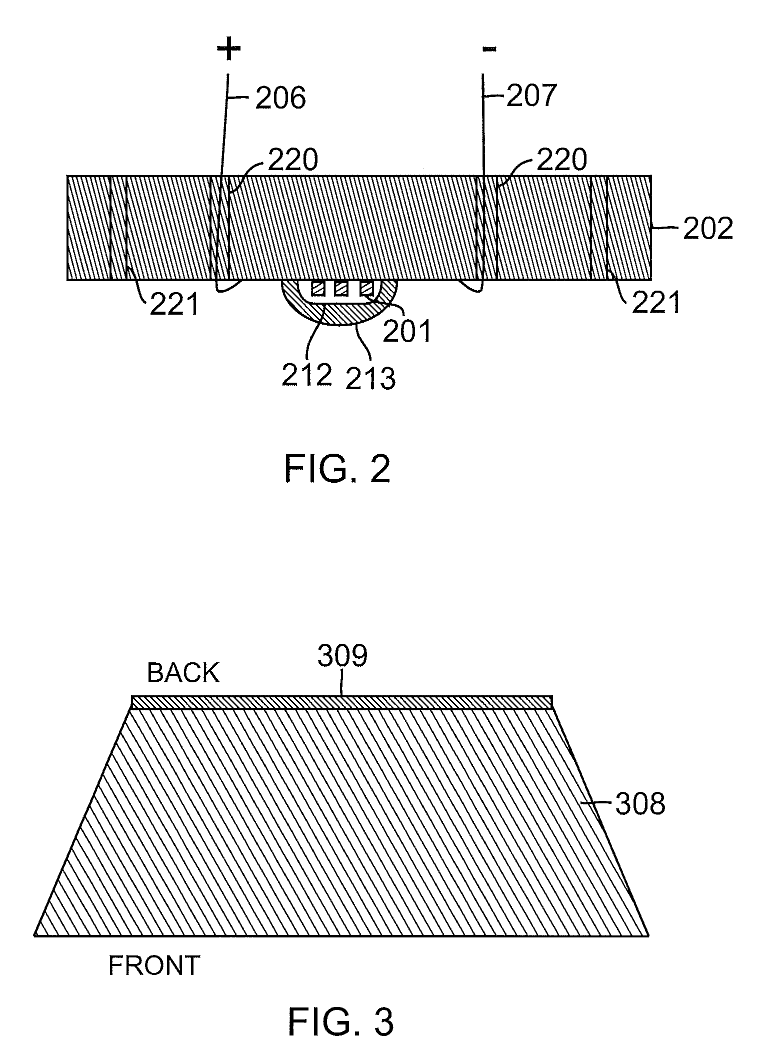
[0023]The temperature of any phosphors that are used to modify the color of light for an LED must be as low as possible so as to provide desired color conversion efficiency. As those skilled in the art will appreciate, the Stokes shift will tend to cause the phosphors to heat up. The Stokes shift is the difference in the energy levels between the absorption spectra and the emission spectra of a fl...


PUM


Abstract

An LED assembly can include a heat sink base, at least one LED die attached to the heat sink base, and a lens. One or more layers of phosphor can be formed upon the lens. A heat sink, such as a finned heat sink, can attach the heat sink base to the lens. Heat from the LED die can flow through the heat sink base to the heat sink, from which the heat can be dissipated. Similarly, heat from phosphors can flow through the lens to the heat sink, from which the heat can be dissipated. By removing heat from the LED die, more current can be used to drive the LED die, thus providing brighter light. By removing heat from the phosphors, desired colors can be more reliably provided.

Description

TECHNICAL FIELD[0001]The present invention relates generally to light emitting diodes (LEDs). The present invention relates more particularly to a heat sink base for enhancing the optical performance of a LED by reducing the temperature of one or more junctions of the LED and / or by reducing the temperature of one or more phosphors of the LED.BACKGROUND[0002]Light emitting diodes (LEDs) are well known. As the cost of LEDs continues to fall and as they become more efficient, more different applications are being found for them and the applications are becoming more sophisticated. For example, LEDs are being used to provide light in such applications as flashlights, displays, and general illumination.[0003]In such applications, LEDs replace light bulbs or lamps. In order to provide the desired amount and quality of light (the amount and quality similar to that provided by light bulbs or lamps), sufficiently bright LEDs are required. However, brighter LEDs require more current and more ...

Claims


Application Information

Patent Timeline
Patent Type & Authority Applications(United States)
IPC IPC(8): H01J7/24H01J9/18
CPCF21K9/00F21Y2101/02H01L33/483H01L33/507H01L33/58H01L2924/19107H01L33/648H01L2924/0002H01L2924/00F21K9/64F21Y2115/10
Inventor SHI, WEI
Owner BRIDGELUX INC
Why Eureka
Try Eureka