Tuning multiport amplifiers

a multi-port amplifier and amplifier technology, applied in amplifiers, amplifiers with semiconductor devices/discharge tubes, amplifiers, etc., can solve the problems of high-challenging problems in ku and ka-band, lack of flexibility, power to beam allocation, interport isolation performance,

Active Publication Date: 2010-08-26
ASTRIUM GMBH
View PDF8 Cites 12 Cited by
  • Summary
  • Abstract
  • Description
  • Claims
  • Application Information

AI Technical Summary

Benefits of technology

[0014]It has been estimated that the method of the invention, requiring only partial matching of amplifiers and hybrids, as it does, is likely to be 20-30% more time efficient in tuning.
[0019]The said step of matching each amplifier to its paired amplifier may be carried out by said matching of paired alternate amplifiers. Where this is the case the said step of matching the paired alternate amplifiers may also include matching signal phase and insertion losses for respective input and output hybrids in both closest connection and next closest connection with each paired amplifier.
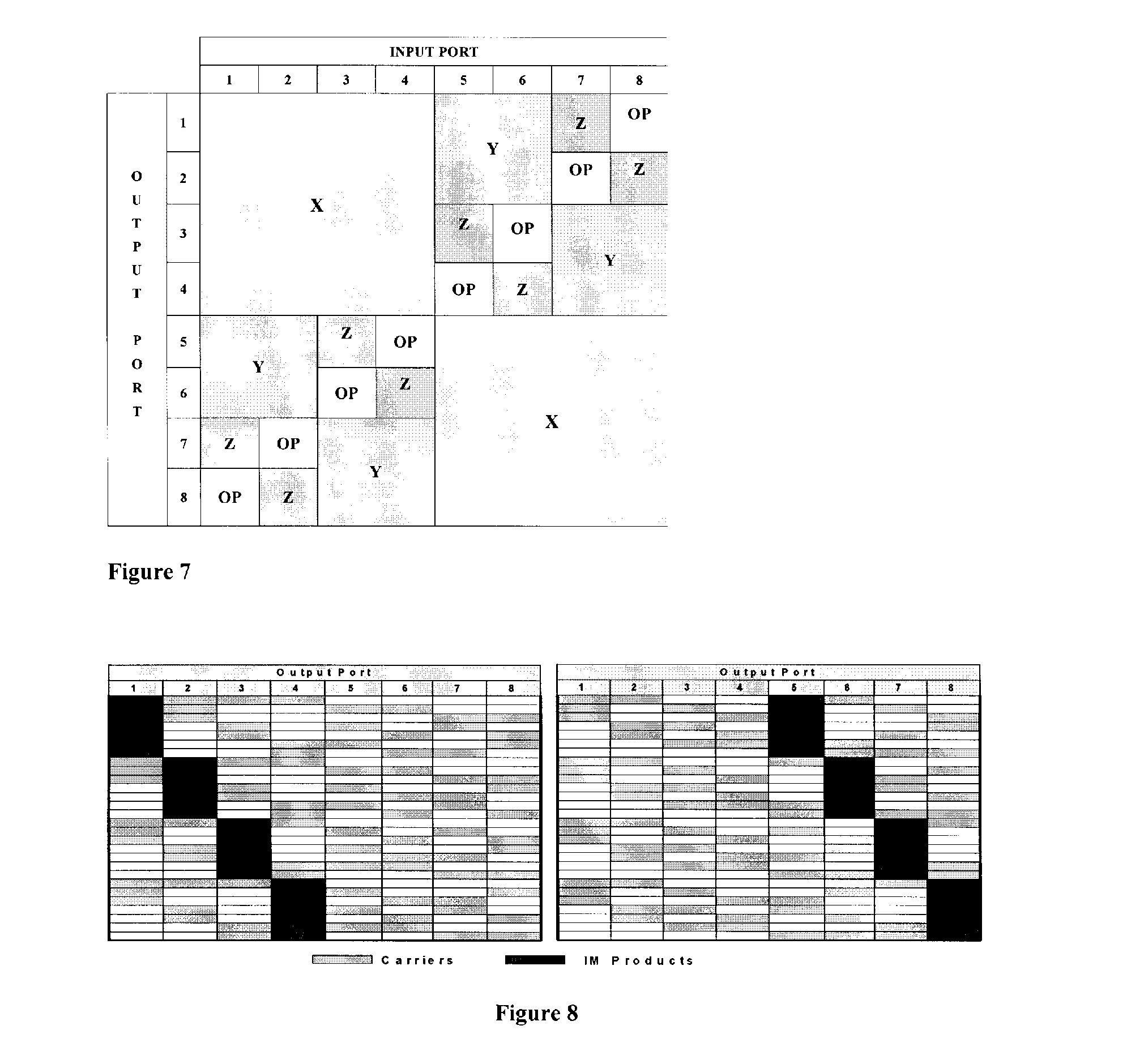
[0034]The isolation analysis presented herein enables output port selection for optimum isolation in multi-beam frequency re-use schemes and the IM analysis assists in the allocation of frequencies to input ports for minimum IM interference.

Problems solved by technology

MPAs have successfully been applied at L and S-band, but present highly challenging problems at Ku and Ka-band at which wavelengths are an order of magnitude shorter.
The essential disadvantage of the SFB is lack of flexibility, particularly power to beam allocation.
The essential problem in the provision of Ku and Ka band MPAs is that of phase and amplitude tracking between the amplifiers and other units at the frequencies concerned (12 GHz at Ku, 20 GHz at Ka-band) and impacts of this tracking on interport isolation performance (the so-called cross talk problem).
It will be appreciated that this will be more time consuming than obtaining the more relaxed matching of the previous three ranges but, in all cases, it is only the paired amplifiers that are matched to the closer limits and in many cases the non paired amplifiers may require no adjustment at all from their manufactured state.
But it will of course be more difficult, and therefore more expensive, to achieve.

Method used


Image

  • Tuning multiport amplifiers
  • Tuning multiport amplifiers
  • Tuning multiport amplifiers

Examples


Embodiment Construction

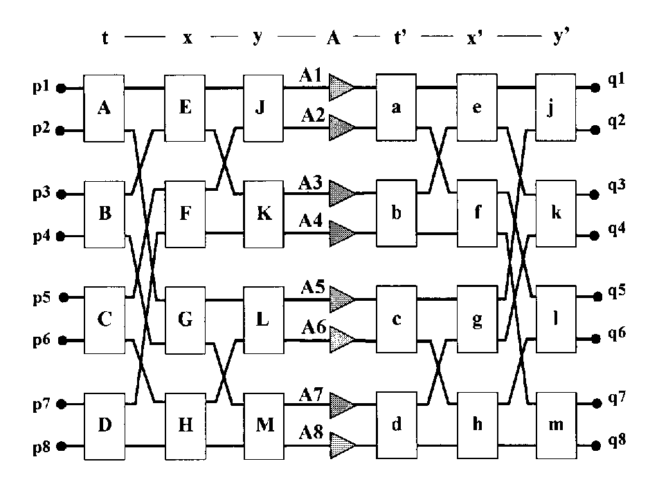
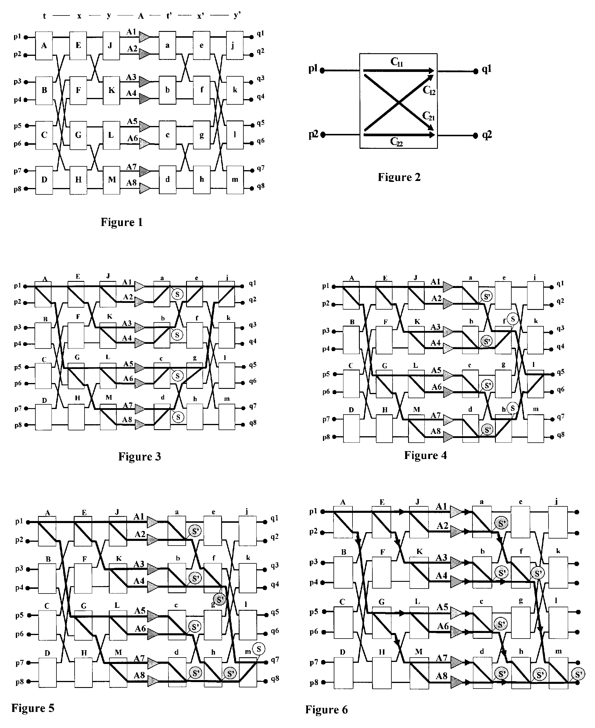
[0044]A diagram of an 8 port MPA is shown FIG. 1. It comprises a set of 3 columns of 4 input hybrids, a single column of 8 amplifiers and a set of 3 columns of 4 output hybrids.

[0045]A definition of a hybrid element (input or output hybrid), is given in FIG. 2. The input and output signals, p1 & p2 and q1 & q2 are assumed to be complex. Transfer function of the hybrid is represented thus:

(q1q2)=(C11C12C21C22)(p1p2)(1)

[0046]where C11, C12, C21, C22 are all invariable complex coefficients which can be represented as follows:

C11=r11·exp j·θ11, C12=j·r12·exp j·θ12, C21=j·r21·exp j·θ21, C22=r22·exp j·θ22  (2)

[0047]Ideally for a perfect hybrid all r=1 / √2, and all θ=0, and the transfer matrix becomes:

T=12(1jj1)(3)

[0048]For a practical hybrids, r and θ will deviate from the ideal, and if the deviations are small (√2 / r<0.2 dB, θ<10°) the following approximations can be made:

C11=(α / √2)(1+σ11+j·θ11), C12=j(α / √2)(1+σ12+j·θ12)  (4)

C21=j(α / √2)(1+σ21+j·θ21), C22=(α / √2)(1+σ22+j·θ22)  (5)

[0049]where...


PUM


Abstract

A method of tuning a multiport amplifier and a multiport amplifier are provided. The multiport amplifier comprises an even number of microwave power amplifiers arranged in parallel, a series of input ports and a series of output ports, the input ports being connected to the amplifiers by a series of input hybrids and the output ports being connected to the amplifiers by a series of output hybrids, whereby an input signal at any given input port is amplified by all amplifiers, and then recombined into an output signal at a given output port. The method includes the steps of matching each amplifier in a pair of adjacent amplifiers to the other to an extent which is greater than matching between non paired amplifiers while still being able to ensure acceptable signal isolation between all output ports. This method of tuning results in an MPA well suited to the requirements of certain frequency re-use schemes and which has a significantly reduced set-up and test time.

Description

FIELD OF THE INVENTION[0001]The present invention relates to tuning multiport amplifiers (MPAs) and in particular to adjusting the phase and gain relationship between individual amplifiers in an MPA to optimise signal isolation between output ports of the MPA.BACKGROUND ART[0002]An MPA is a well-known power amplifier device used for satellite communications, which may operate at microwave frequencies above 1 GHz, and covering L & S bands with frequencies in the range of 1.5-2.6 GHz, and Ku & Ka bands with frequencies in the region 12-20 GHz, etc.[0003]An MPA includes a number N of similar amplifier units (TWT or solid state) in parallel, each having a power P, so that each input signal is amplified by each amplifier, to increase the power of each output signal by a factor N, to P×N. N input ports and N output ports are provided, so that an input signal on one input port is routed to the corresponding output port. The input ports are connected to the amplifier units by a low power in...

Claims


Application Information

Patent Timeline
Patent Type & Authority Applications(United States)
IPC IPC(8): H03F3/68
CPCH03F3/602H03F3/68
Inventor COUCHMAN, ALAN DAVIDJONES, DARYL RICHARD
Owner ASTRIUM GMBH
Why Eureka
Try Eureka