Sensor and method of sensing

a sensor and sensing technology, applied in the field of sensing sensors, can solve the problems of increasing the cost of additional components, affecting the accuracy of capacitance measurements, so as to reduce the effect of noise signals

Active Publication Date: 2010-08-26
NEODRON LTD
View PDF27 Cites 56 Cited by
  • Summary
  • Abstract
  • Description
  • Claims
  • Application Information

AI Technical Summary

Benefits of technology

[0011]According to the present invention there is provided a sensor which is arranged to determine the presence of an object from a change in a capacitance of a sensing element. The sensor comprises a capacitance measurement circuit operable to perform measurement cycles to measure a capacitance of the sensing element, and a controller circuit. The control circuit is operable to detect a periodic noise signal induced on the sensing element, to determine a first part of a repeating pattern of the periodic noise signal, which causes a change in an amount of charge present on the sensing element, which affects the measurement of the capacitance of the sensing element by the capacitance measurement circuit, to determine a second part of the repeating pattern of the periodic noise signal, which does not cause a change in the amount of charge present on the sensing element, and to control the measurement cycles of the capacitance measurement circuit to perform the measurement cycles during the second part of the periodic noise signal and not to perform the measurement cycles during the first part of the periodic noise signal. The sensor is therefore arranged to detect a repeating pattern of the periodic noise signal induced on the key, and to synchronise the generation of a plurality of measurement cycles to reduce the effects of the noise signal on the measurement of the change in the capacitance of the sensing element.
[0015]In one example the sensing element includes a key and the controller is operable to control the capacitance measurement circuit to detect a change in the capacitance of the sensing element by generating one or more measurement bursts, each measurement burst providing a plurality of measurement cycles, each measurement cycle including inducing charge onto the key during a charging part of a measurement cycle, measuring an amount of charge induced on the key during a signal measurement part of the measurement cycle, and detecting the presence of the object proximate the key from a change in an amount of charge transferred from the key, thereby to detect a change in the capacitance of the sensing element. The sensor is therefore arranged to detect a repeating pattern of the periodic noise signal induced on the key, during a noise sensing phase, and to synchronise the generation of the plurality of bursts and the measurement cycles within the bursts to reduce the effects of the noise signal on the measurement of the change in the capacitance of the sensing element. The sensor can be used to form a two dimensional touch sensor, which can be overlaid on a liquid crystal display (LCD) screen. As such, the effects of switching noise on the detection of an object, caused by a common voltage signal of the LCD screen can be reduced.
[0018]In one example the noise signal is detected from the key itself. For the example of LCD noise which provides a periodic noise pattern, the proximity of the LCD screen with respect to the touch sensor, which may for example form part of a touch sensitive display, will induce a significant noise signal, on the key. By providing an arrangement in which the periodic noise signal can be detected during an initialization phase of the touch sensor, the measurement of capacitively induced charge present on the key, which utilizes a plurality of measurements cycles within bursts, can be synchronised with the noise signal. The synchronisation, can for example therefore avoid rising and falling edges of the periodic noise. As a result, for example, a two dimensional touch sensor can be manufactured and designed separately from the LCD screen with the advantage that physical electrical coupling which would otherwise be required between the touch sensor detection circuit and the LCD screen is not required.
[0019]In contrast to what is disclosed in EP 1 821 175 [7] as mentioned above, embodiments of the present invention do not require a noise detector circuit to be connected to address and / or switching signals produced to activate LCD pixels of an LCD screen. Thus, in EP 1 821 175 [7] a connection is required to the common voltage and preferably to the horizontal synchronization signal of the LCD switching circuit to generate a strobe signal which is used to blank out a current signal which is used to the detect the presence and position of an object. In contrast, the present technique can detect the noise signal from the capacitive key itself, thereby providing an arrangement in which the touch sensitive 2DCT sensor is self contained with respect to the LCD screen and the associated driving and control circuit.

Problems solved by technology

However, it has been found that there are some limitations associated with 2DCT sensors which operate on passive sensing techniques.
Furthermore, electrical noise generated from such LCD screens can interfere with capacitance measurements when a pointing object approaches the screen.
Furthermore; additional steps are required during manufacture and as a result there is an increased cost due to further components being needed.
Generally, a technical problem subsists in the implementation of touch sensors to reduce the effects of noise signals, which may be induced from another source on a sensing element of the touch sensor.

Method used


Image

  • Sensor and method of sensing
  • Sensor and method of sensing
  • Sensor and method of sensing

Examples


Embodiment Construction

[0038]As explained above there are various forms of touch sensors which can determine the presence of a body proximate a sensing element of the touch sensor as a result of a change of charge transferred from a key of the touch sensor. The following description with reference to FIGS. 1 to 4 provides a background explanation of the operation of touch sensors according to a first example and FIGS. 13 and 14 provide other example touch sensors with which embodiments of the present invention find application.

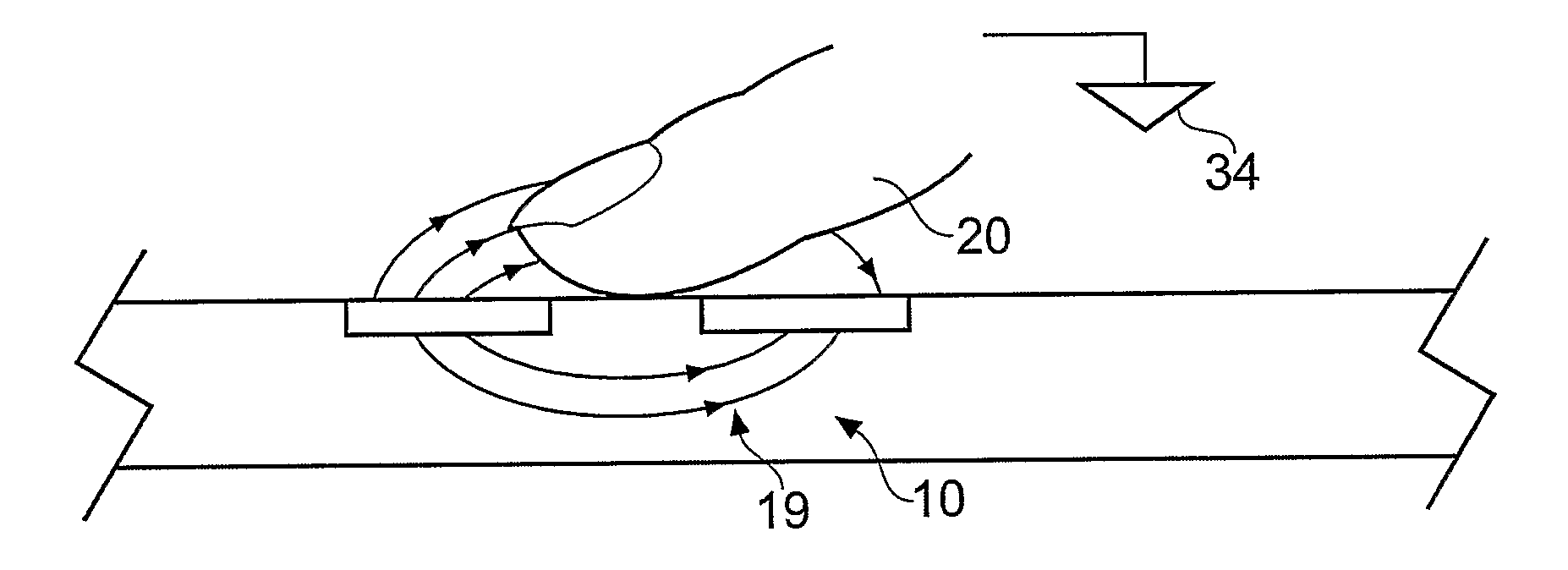
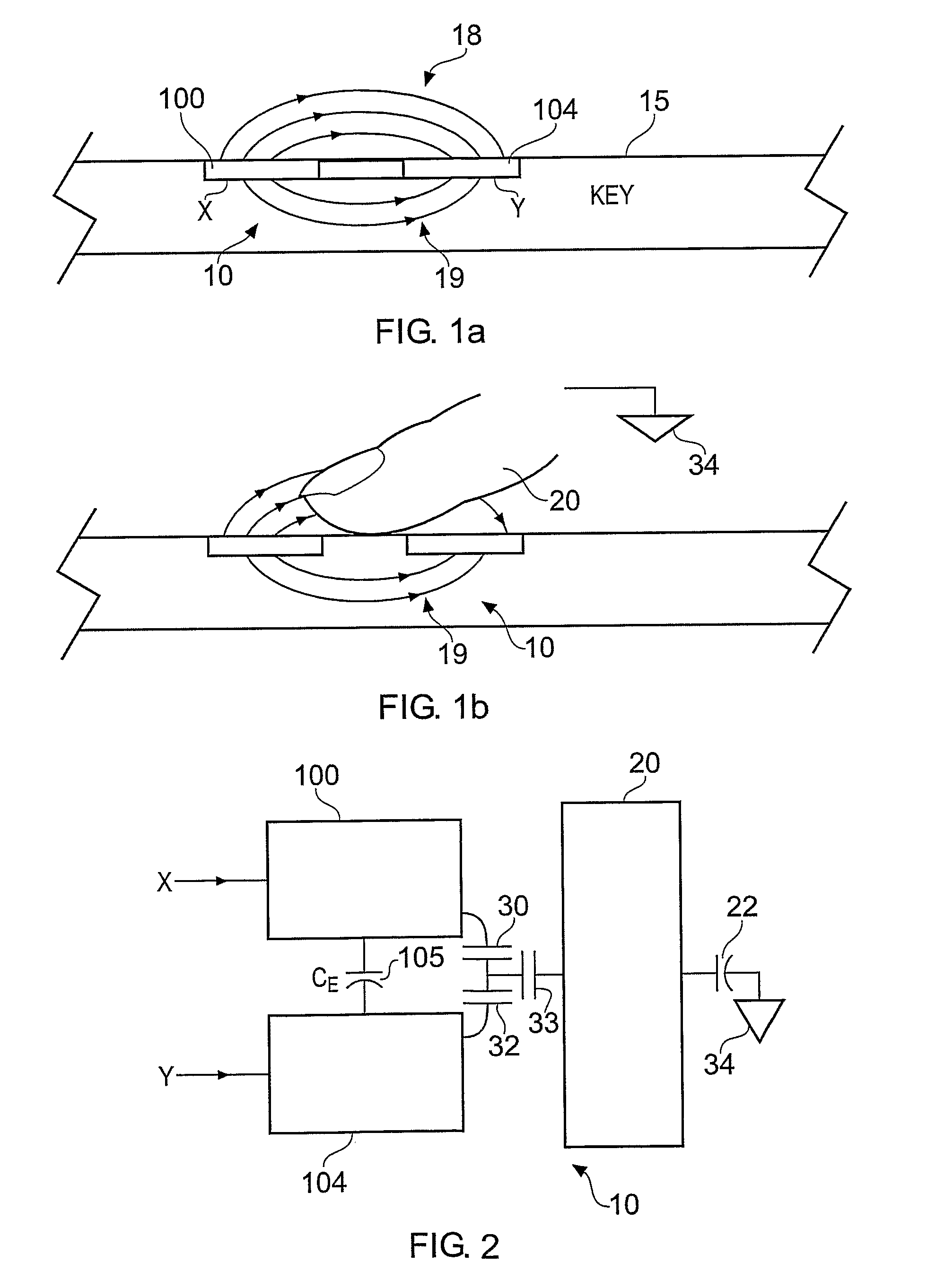
[0039]An example of such a touch sensor is shown in FIG. 1a and 1b. The example shown in FIGS. 1a and 1b correspond to an example in which a pair of transverse electrodes form a touch sensor. As shown in FIG. 1a a pair of electrodes 100, 104 which form a drive or X plate and a receiving or Y plate in the following description are disposed beneath the surface of a touch sensitive control panel 15. As shown in FIG. 1a and 1b the touch sensor 10 is arranged to detect the presence of a ...


PUM


Abstract

A sensor is arranged to determine the presence of an object from a change in a capacitance of a sensing element. The sensor includes a capacitance measurement circuit operable to perform measurement cycles to measure a capacitance of the sensing element, and a controller circuit. The control circuit is operable to detect a periodic noise signal induced on the sensing element, to determine a first part, of a repeating pattern of the periodic noise signal, which causes a change in an amount of charge present on the sensing element, which affects the measurement of the capacitance of the sensing element by the capacitance measurement circuit, to determine a second part of the repeating pattern of the periodic noise signal, which does not cause a change in the amount of charge present on the sensing element, and to control the measurement cycles of the capacitance measurement circuit to perform the measurement cycles during the second part of the periodic noise signal and not to perform the measurement cycles during the first part of the periodic noise signal.

Description

FIELD OF THE INVENTION[0001]The present invention relates to sensors and methods for sensing the presence of an object from a change in a capacitance of a sensing element. The present invention also relates to sensors, which include a plurality of keys, which can be arranged in a matrix and can be used to form, for example, a two dimensional touch sensitive user input device.[0002]In some embodiments a touch sensor includes a key comprising a drive plate and a sense plate, in which the key may be driven contemporaneously with charge measurement taking place or a charge signal may be measured after a key is driven during a measurement cycle.[0003]In some embodiments a touch sensor includes a sensing circuit for use in reducing the effects of noise. In some examples the noise may be induced by another component, such as, for example, a liquid crystal display (LCD) screen, when the touch screen is used to form a touch sensitive display screen.BACKGROUND OF THE INVENTION[0004]There are ...

Claims


Application Information

Patent Timeline
Patent Type & Authority Applications(United States)
IPC IPC(8): G06F3/045
CPCG06F3/0416G09G3/3611G06F3/044G06F3/0418G06F3/04184G06F3/0446
Inventor PHILIPP, HARALDYILMAZ, ESAT
Owner NEODRON LTD
Why Eureka
Try Eureka