Reinforced micro-mechanical part

a micro-mechanical and reinforcement technology, applied in the field of micro-mechanical parts, can solve the problems of shock resistance of silicon, and achieve the effect of increasing the mechanical properties of said parts

Active Publication Date: 2010-08-26
ETA SA MFG HORLOGERE SUISSE
View PDF10 Cites 42 Cited by
  • Summary
  • Abstract
  • Description
  • Claims
  • Application Information

AI Technical Summary

Benefits of technology

[0008]It is an object of the present invention to provide a solution that aims to improve the mechanical resistance of a silicon micro-mechanical part and in particular its resistance to shocks.
[0010]The invention also concerns a method for manufacturing a reinforced silicon part according to claim 2. This method enables the formation, in particular by thermal oxidation, the thick amorphous layer which considerably increases the mechanical properties of said part as will be explained in the following detailed description.

Problems solved by technology

Silicon is however known to be sensitive to shocks, which may be necessary during assembly, inevitable in operation or accidental when for example the user knocks his wristwatch against something or drops it.

Method used


Image

  • Reinforced micro-mechanical part
  • Reinforced micro-mechanical part

Examples


Embodiment Construction

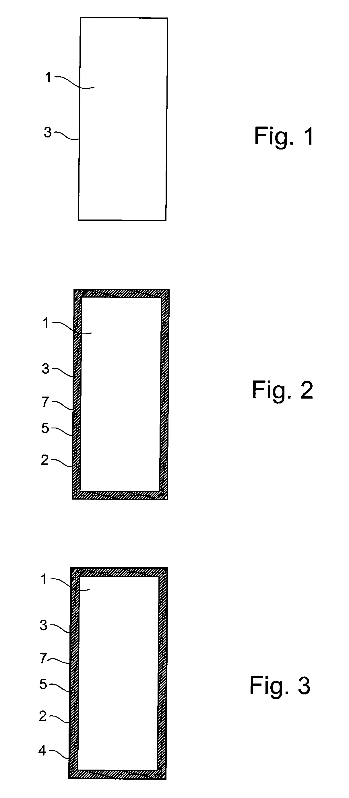
[0015]A hairspring mounted in a horological movement the malfunction of which is very easy to detect, simply by observing the movement stop if the hairspring happens to break, as will be explained hereinafter, has been taken here by way of example.

[0016]The hairspring is obtained by known etching techniques from a silicon plate of slightly smaller thickness than the desired final height for the hairspring.

[0017]One could for example use the reactive ionic etching technique (RIE) and give the hairspring the shape which is considered most appropriate, as disclosed for example in International Patent Application W02004 / 070476.

[0018]Given the very small dimensions of a hairspring, a batch of hairsprings can be manufactured in one time on the same plate.

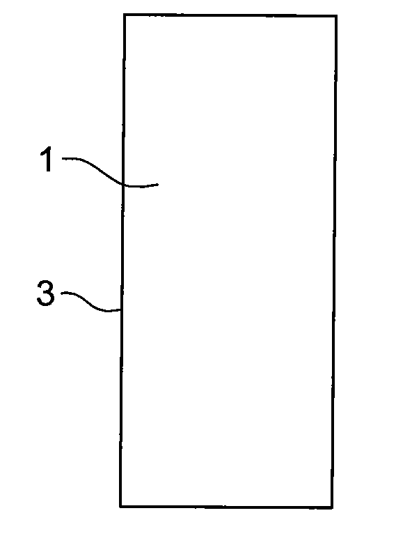
[0019]FIG. 1 shows the cross-section of a hairspring having a core made of silicon, reference 3 designating the initial external surface. When this hairspring is left for a certain amount of time in the surrounding air, it naturally cover...


PUM

PropertyMeasurementUnit
temperatureaaaaaaaaaa
thicknessaaaaaaaaaa
thicknessaaaaaaaaaa

Abstract

The micro-mechanical part, for example a horological movement part, includes a silicon core (1) all or part of the surface (3) of which is coated with a thick amorphous material (2). This material is preferably silicon dioxide and has a thickness which is five times greater than the thickness of native silicon dioxide.

Description

[0001]This is a National Phase Application in the United States of International Patent Application PCT / EP 2006 / 005959 field Jun. 21, 2006, which claims priority on European Patent Application No. 05013912.0, filed Jun. 28, 2005. The entire disclosures of the above patent applications are hereby incorporated by reference.TECHNICAL FIELD[0002]The present invention concerns a micro-mechanical part made of silicon, said part having been treated in order to give improved mechanical properties. It is for example, but in a non limitative manner, a micro-mechanical part for a horological mechanical movement, i.e. either a part having an active function for example for transmitting and / or transforming an energy to drive hands in order to give a time indication in connection with a dial, or a passive part for example for positioning wheel sets.BACKGROUND OF THE INVENTION[0003]Silicon is a material which is used more and more often in the manufacture of mechanical parts and in particular of m...

Claims


Application Information

Patent Timeline
Patent Type & Authority Applications(United States)
IPC IPC(8): G04B15/14B44C1/22
CPCB81C1/00682C30B29/06C30B33/005G04B17/066G04D3/0074G04B13/02G04B15/14G04D3/0069G04B13/022
Inventor RAPPO, RENELIPPUNER, MARCPARATTE, LIONELCONUS, THIERRY
Owner ETA SA MFG HORLOGERE SUISSE
Why Eureka
Try Eureka