Connector device and connector assembly

a technology of connectors and connectors, applied in the direction of coupling device connections, connection contact member materials, coupling protective earth/shielding arrangements, etc., can solve the problem of insufficient shielding performance for noise removal in some cases, and achieve the effect of improving shielding performance and well-balanced

Active Publication Date: 2010-08-26
SUMITOMO WIRING SYST LTD
View PDF3 Cites 34 Cited by
  • Summary
  • Abstract
  • Description
  • Claims
  • Application Information

AI Technical Summary

Benefits of technology

[0006]The invention relates to a connector device with a connector to be mounted on a conductive case that has a device therein. The connector is covered substantially by at least first and second shield shells and a second shield shell. Connecting portions connect the first and second shield shells at three or more positions. The connecting portions are arrange

Problems solved by technology

The first and second shield shells are in contact at only two points and h

Method used


Image

  • Connector device and connector assembly
  • Connector device and connector assembly
  • Connector device and connector assembly

Examples


Embodiment Construction

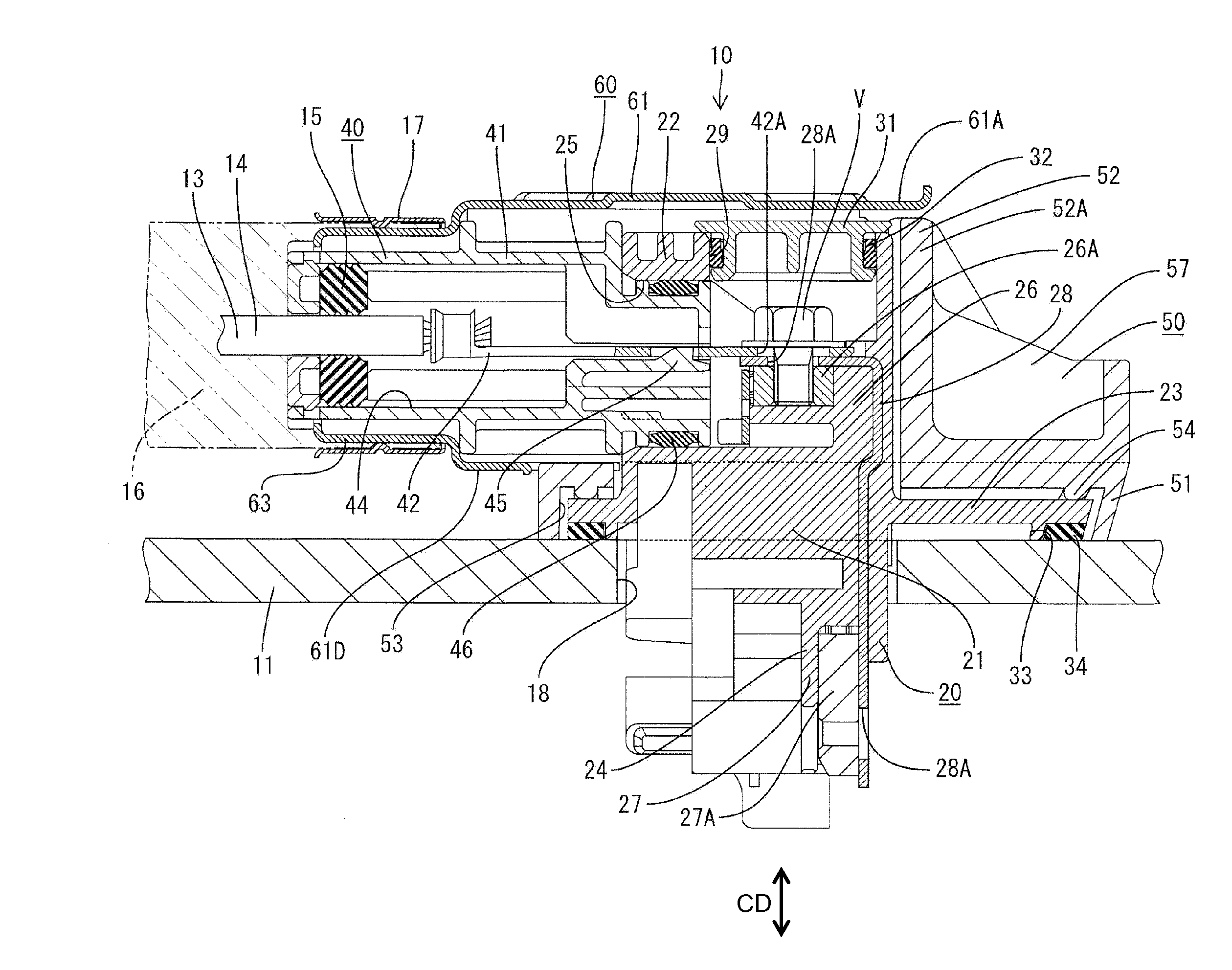
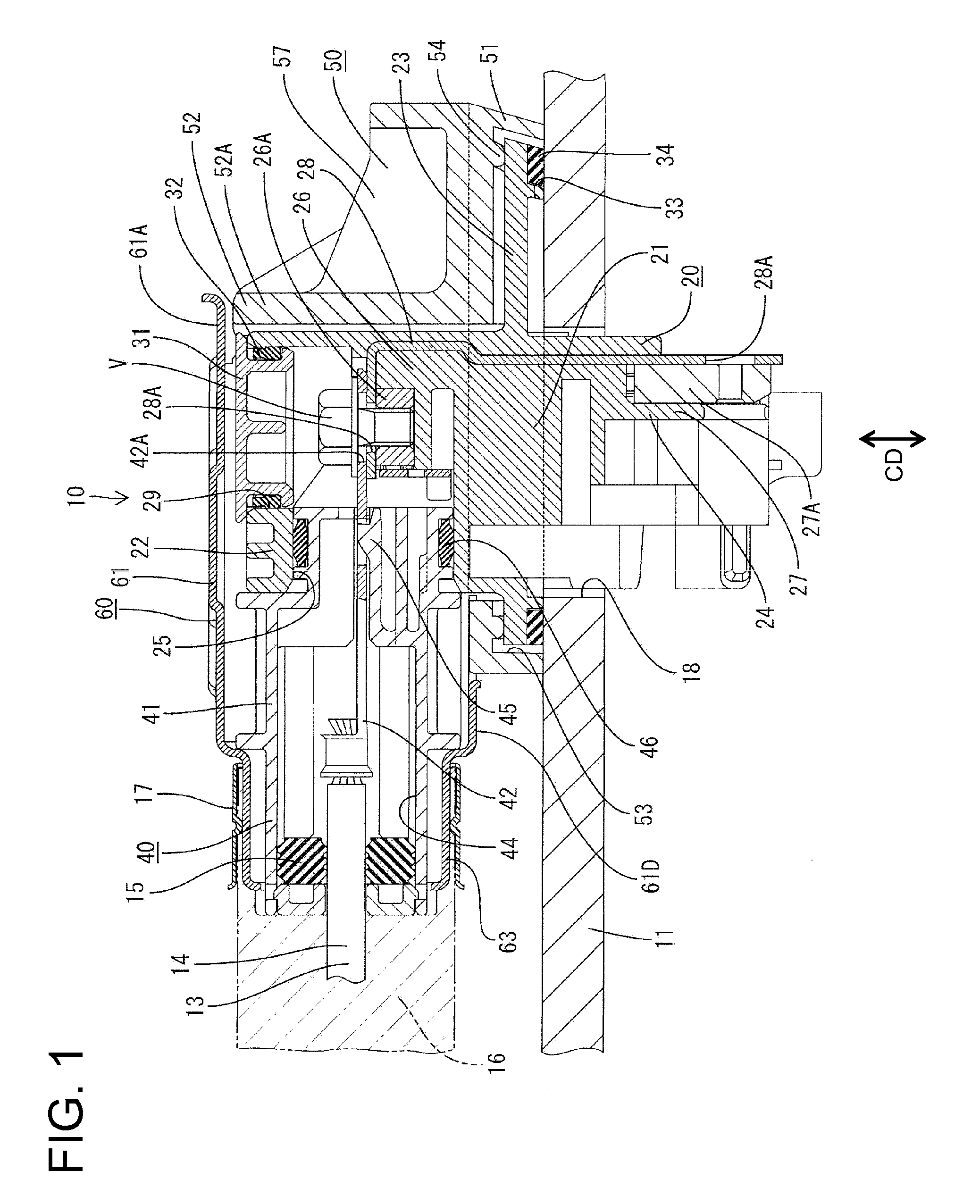
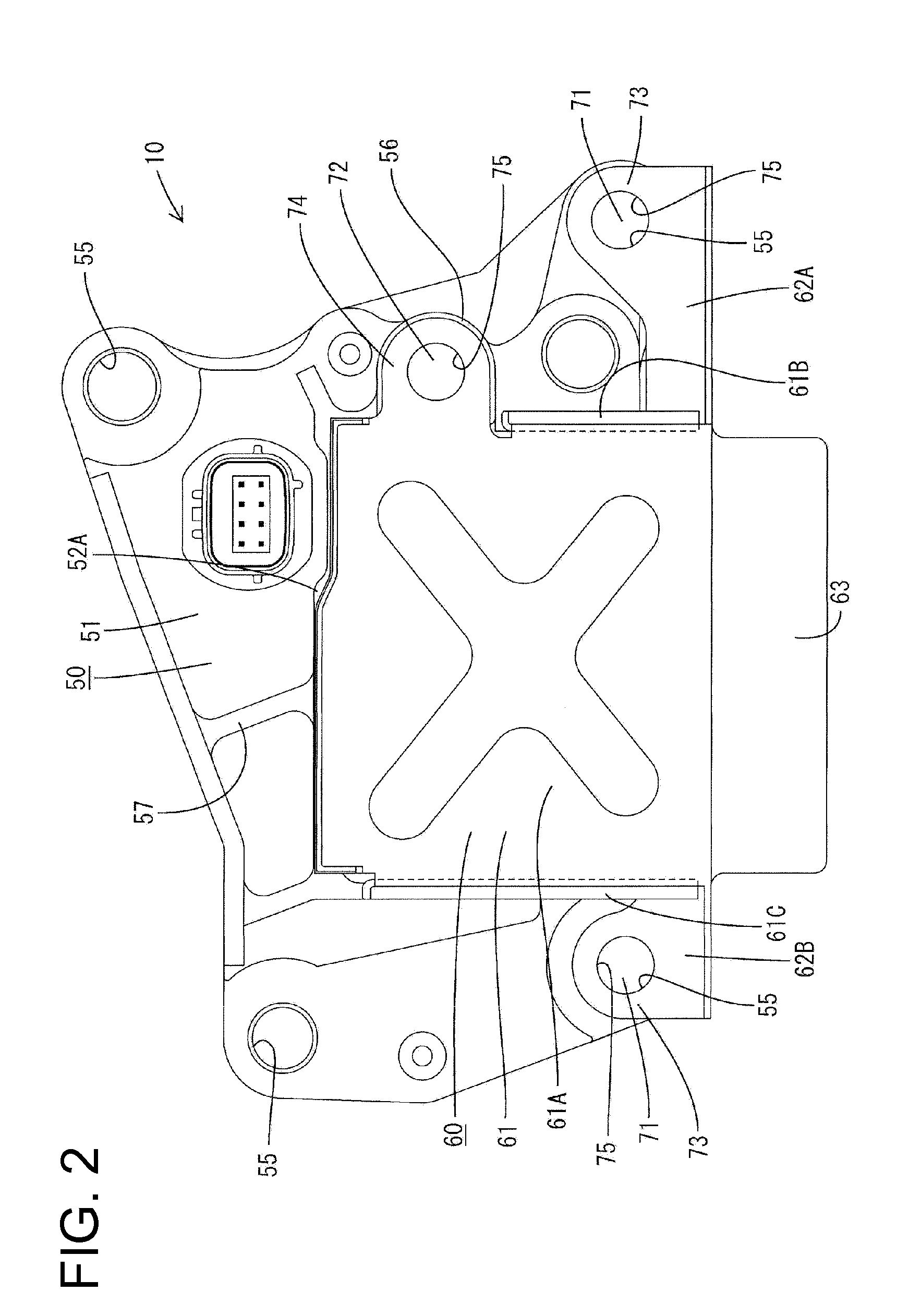
[0026]A connector device according to the invention is identified by the numeral 10 in FIGS. 1 to 3. The connector device 10 is to be mounted on a conductive metal case 11 that accommodates an unillustrated motor and is connected electrically with the motor and / or with an unillustrated electric or electronic control unit (ECU) for controlling the motor, such as for supplying driving power to the motor. In the following description, upper and lower sides of FIG. 1 are referred to as upper and lower sides.

[0027]The connector device 10 has a device side connector 20 to be mounted on the case 11. The device side connector 20 is covered by first and second shield shells 50 and 60. A power supply side connector 40 is external and separate from the connector device 10, but is connected to the device side connector 20.

[0028]The device side connector 20 has a device side housing 21 made e.g. of synthetic resin. The device side housing 21 includes a connecting portion 22 substantially in the ...


PUM


Abstract

A connector device (10) has a connector (20) to be mounted on a metal case (11) that accommodates a device therein and is covered by a first shield shell (50) and a second shield shell (60). Connecting portions for connecting the first and second shield shells (50, 60) are provided at least at three positions and these connecting portions are arranged at positions displaced in a connecting direction of the connector (20) and a mating connector (40) and a direction orthogonal to the connecting direction. The connecting positions of the first and second shield shells (50, 60) are well-balanced to provide a good a shielding performance.

Description

BACKGROUND OF THE INVENTION[0001]1. Field of the Invention[0002]The invention relates to a connector device including a shield structure and to a connector assembly.[0003]2. Description of the Related Art[0004]Japanese Unexamined Patent Publication No. 2006-196198 discloses a connector device with a shield structure for shielding high-frequency noise. The connector device has a connector that is mounted on a case that contains a motor. A first shield shell is fixed to the case and covers a rear part of the connector. A second shield shell is connected to the first shield shell and covers a front part of a connector. Two contact pieces in the form of leaf springs are provided at the rear of the second shield shell and contact the first shield shell to connect the first and second shield shells electrically. The first and second shield shells are in contact at only two points and hence shielding performance for noise removal is insufficient in some cases.[0005]The invention was develo...

Claims


Application Information

Patent Timeline
IPC IPC(8): H01R13/648
CPCH01R13/6593H01R9/032H01R13/65912
Inventor KAWAMURA, MASAYUKIMATSUOKA, HIROYUKI
Owner SUMITOMO WIRING SYST LTD
Why Eureka
Try Eureka