Actuator for moving body in tube, method for controlling the same, and endoscope

a technology for moving bodies and endoscopes, which is applied in the field of actuators for moving bodies in tubes, can solve the problems of difficult to generate engagement force from one balloon, and the effect of reducing the projection amount of folds and significantly reducing the effect of drawing

Inactive Publication Date: 2010-08-26
YAMAKAWA SHINICHI +4
View PDF2 Cites 10 Cited by
  • Summary
  • Abstract
  • Description
  • Claims
  • Application Information

AI Technical Summary

Benefits of technology

[0008]However, when the plurality of variable tubes are only vertically moved, almost no effect of moving the contact surface of the tube is obtained. The effect of the drawing can be obtained only when the fold of the intestinal tract is made to efficiently enter the groove between the expanded tubes. However, almost no fold exists in the sigmoid colon. Further, as the intestinal tract is straightened in the process of being drawn, the projection amount of the fold is reduced, so that the effect of the drawing is significantly reduced. Therefore, it is difficult that one balloon is made to generate engagement force so as to engage with the intestinal wall and is also made to generate propulsive force so as to move relatively to the intestinal wall.

Problems solved by technology

However, when the plurality of variable tubes are only vertically moved, almost no effect of moving the contact surface of the tube is obtained.
Therefore, it is difficult that one balloon is made to generate engagement force so as to engage with the intestinal wall and is also made to generate propulsive force so as to move relatively to the intestinal wall.

Method used


Image

  • Actuator for moving body in tube, method for controlling the same, and endoscope
  • Actuator for moving body in tube, method for controlling the same, and endoscope
  • Actuator for moving body in tube, method for controlling the same, and endoscope

Examples


first embodiment

[0077]First, a first embodiment will be described. In the first embodiment, the number of balloons is set to two.

example 1

Configuration of Actuator for Moving Body in Tube

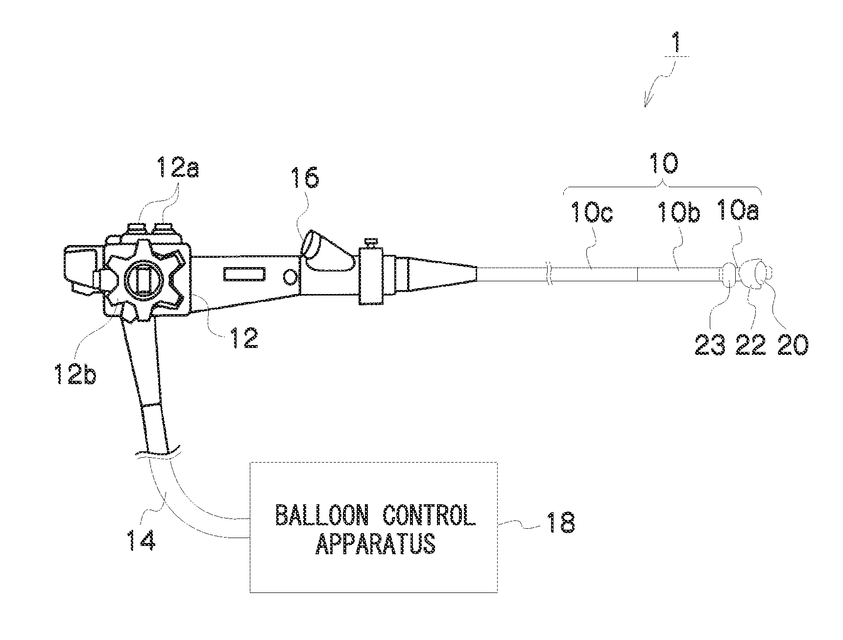
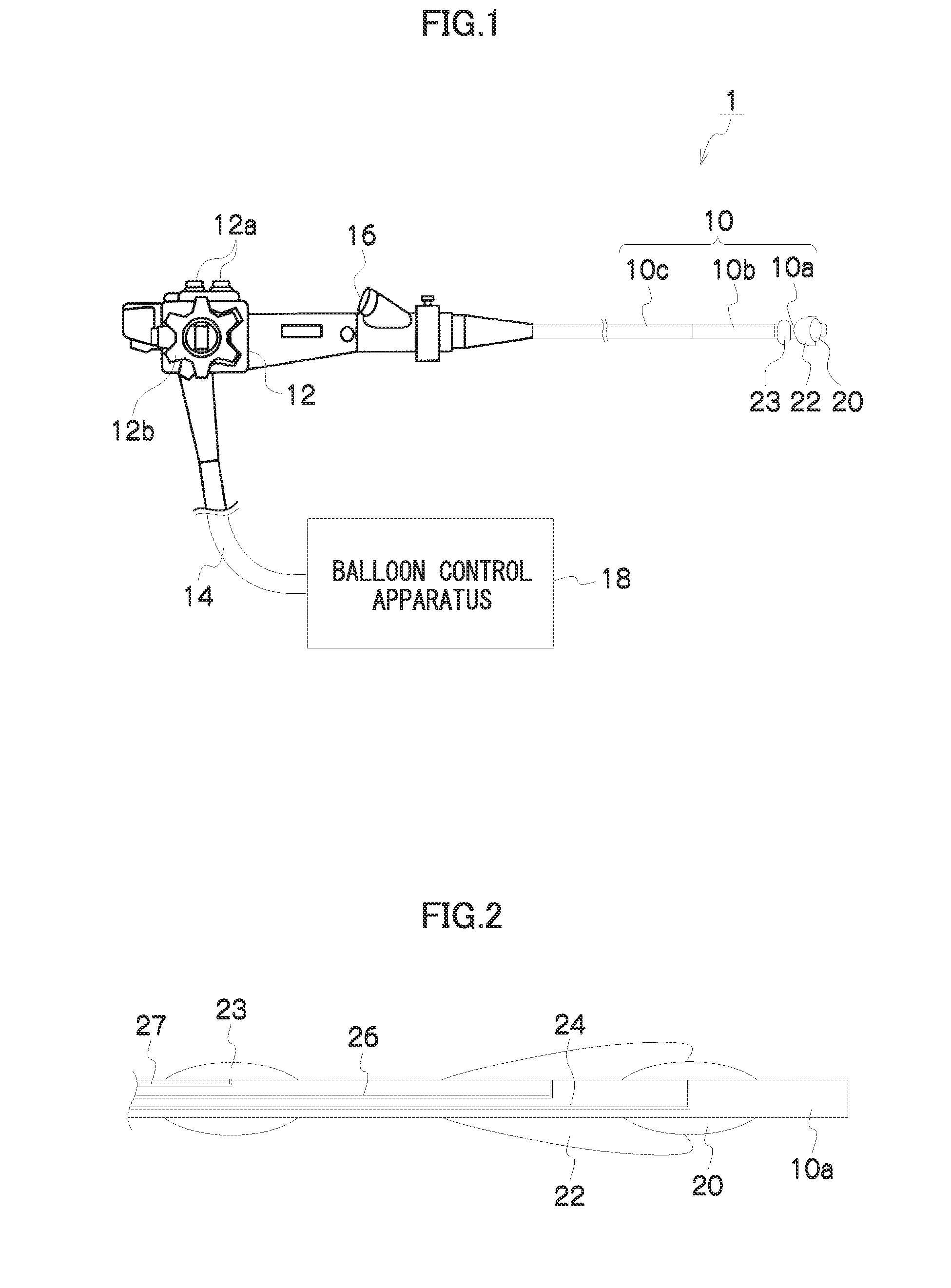
[0078]FIG. 2 is an enlarged sectional view showing the distal end section 10a of the insertion section 10 of example 1 according to a first embodiment. As shown in FIG. 2, in example 1, two balloons of the drive balloon 20 and the engagement balloon 22 are provided at the distal end section 10a of the insertion section 10 in this order from the front in the advance direction of the distal end section 10a.

[0079]Further, there is also provided a holding balloon 23 which holds the position of the distal end section 10a of the insertion section 10 substantially at the center inside the tube at the time when the drive balloon 20 and the engagement balloon 22 are not brought into contact with the tube wall.

[0080]The drive balloon 20, the engagement balloon 22, and the holding balloon 23 are all made of freely expandable and contractible latex rubber.

[0081]The engagement balloon 22 is a balloon having an expansion characteristic of being ab...

example 2

[0105]In example 2, unlike example 1, a balloon having directivity in the direction of deformation at the time of expansion and contraction is used in place of the drive balloon 20.

[0106]FIG. 6 is an enlarged sectional view showing the distal end section 10a of the insertion section 10 in example 2 according to the first embodiment. As shown in FIG. 6, example 2 is different from example 1 in that a directed drive balloon 28 is provided in place of the drive balloon 20.

[0107]The directed drive balloon 28 and the engagement balloon 22 are formed in the entire circumferential direction of the insertion section 10. It is preferred that the directed drive balloon 28 is arranged adjacent to the inside of the engagement balloon 22.

[0108]The directed drive balloon 28 is made of natural rubber such as latex rubber. However, the directed drive balloon 28 is configured to have a portion having a thickness larger than the other portion thereof, and thereby, has directivity in the direction of ...


PUM


Abstract

An aspect of the actuator for the moving body in tube according to the present invention is characterized by including: a first expansion/contraction member which includes a first portion that fills between the moving body in tube and the tube wall at the time of being expanded to come into contact with the tube wall, and a second portion that is brought into contact with the tube wall to generate propulsive force, and a part of which is fixed to the moving body in tube; a drive device which drives the first expansion/contraction member; and a control section which controls the first expansion/contraction member and the drive device, and is characterized in that the control section performs control so that the first portion of the first expansion/contraction member is made to become the second portion by the drive by the drive device so as to change the relative position between the moving body in tube and the tube wall.

Description

BACKGROUND OF THE INVENTION[0001]1. Field of the Invention[0002]The present invention relates to an actuator for a moving body in tube, a method for controlling the actuator, and an endoscope. More particularly, the present invention relates to a technique to effect movement in a tube by transmitting propulsive force to the tube wall.[0003]2. Description of the Related Art[0004]The insertion of an endoscope into the large intestine is very difficult because the large intestine is wound in the body and because a part of the large intestine is not fixed to a body cavity. Therefore, much experience is required to acquire the insertion technique. When the insertion technique is insufficient, it causes significant pain to the patient.[0005]Portions of the large intestine, in which portions the endoscope insertion is said to be difficult, are the sigmoid colon and the transverse colon. Unlike other colons, the sigmoid colon and the transverse colon are not fixed in the body cavity. Theref...

Claims


Application Information

Patent Timeline
Patent Type & Authority Applications(United States)
IPC IPC(8): A61B1/005
CPCA61B1/31A61B1/00156
Inventor YAMAKAWA, SHINICHIASHIDA, TSUYOSHINAKAMURA, TAKAYUKIMIYAKO, KUNIAKIMORIMOTO, YUYA
Owner YAMAKAWA SHINICHI
Why Eureka
Try Eureka