Inflatable surgical retractor

a retractor and surgical technology, applied in the field of retractors, can solve the problems of increasing the time of recovery and pain of patients, affecting the efficiency of surgical operations, and affecting the patient's recovery, so as to achieve quick and easy removal of retractors, faster recovery, and faster healing

Inactive Publication Date: 2010-08-26
DIGNITY HEALTH
View PDF16 Cites 24 Cited by
  • Summary
  • Abstract
  • Description
  • Claims
  • Application Information

AI Technical Summary

Benefits of technology

[0010]The invention further includes means to quickly and easily remove the retractor following the end of the surgical procedure and a method for treating the retractor surfaces, prior to insertion, to help stave infection and provide a quicker recovery with faster healing. As well as a device that can be used to help perform all of the heating, expansion and cooling functions to the retractor; in the form of an expansion device having means to provide heated solution, expansion capabilities, and cooling solution sequentially to create the necessary pliability, enlarge the retractor and then cool the retractor to fix it into position during the surgical procedure.

Problems solved by technology

However, techniques for accomplishing such surgery have often been hampered by the need to provide a stable opening from an outer surface, such as the skin or the muscle through to the area of surgical interest, without causing damage to tissue there between.
Such use of mechanical retractors tends to cause damage to skin surfaces and increases the time of recovery and pain that the patient feels.
Further, the size of the incision needed to create the appropriately sized opening through which surgery will proceed can increase the amount of bleeding and oozing in the wound, cause tears in skin and muscle and provide a site for post-operative infections.

Method used


Image

  • Inflatable surgical retractor
  • Inflatable surgical retractor
  • Inflatable surgical retractor

Examples


Embodiment Construction

[0026]While the present invention is susceptible of embodiment in various forms, there is shown in the drawings a number of presently preferred embodiments that are discussed in greater detail hereafter. It should be understood that the present disclosure is to be considered as an exemplification of the present invention, and is not intended to limit the invention to the specific embodiments illustrated. It should be further understood that the title of this section of this application (“Detailed Description of an Illustrative Embodiment”) relates to a requirement of the United States Patent Office, and should not be found to limit the subject matter disclosed herein.

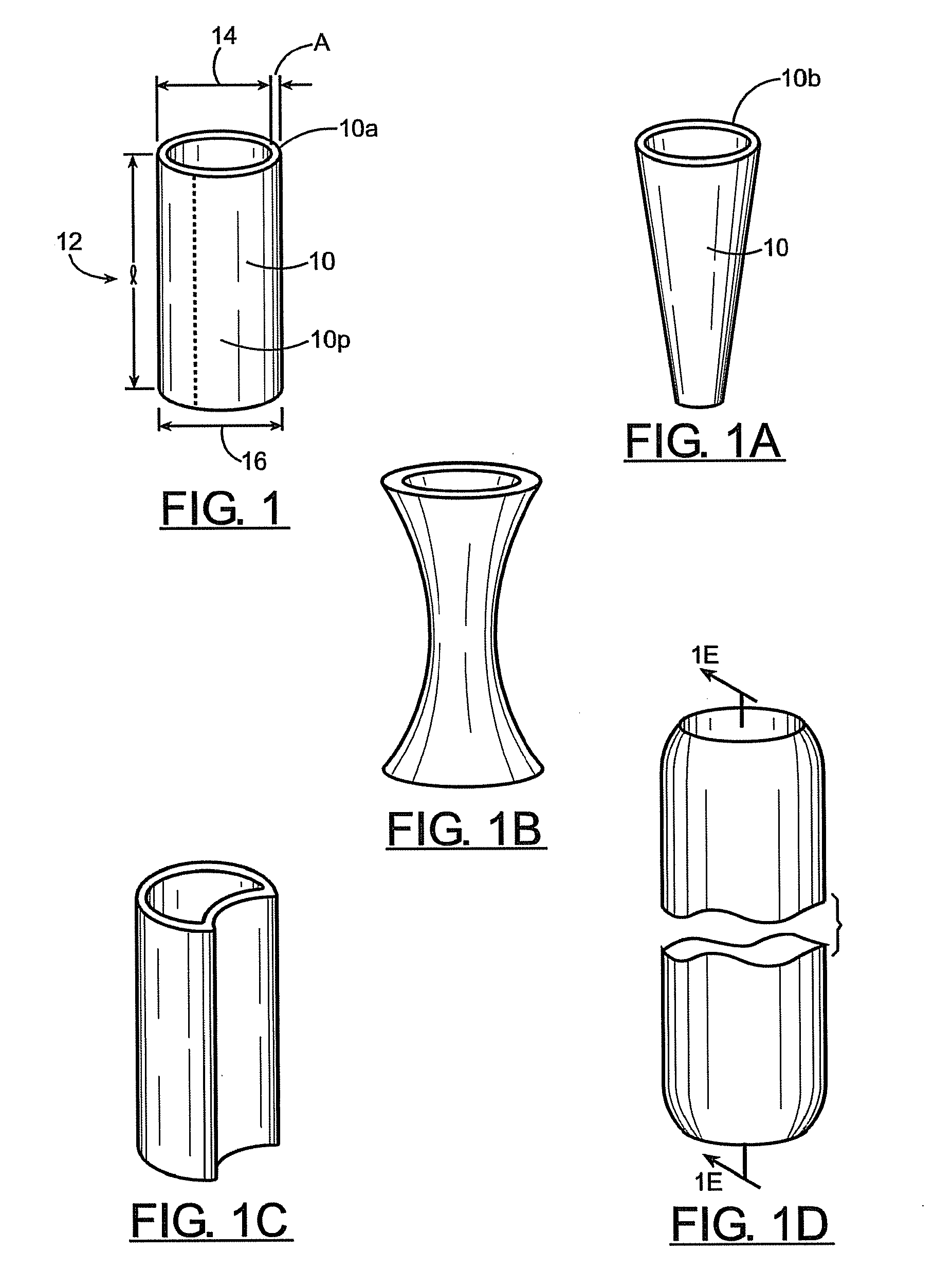
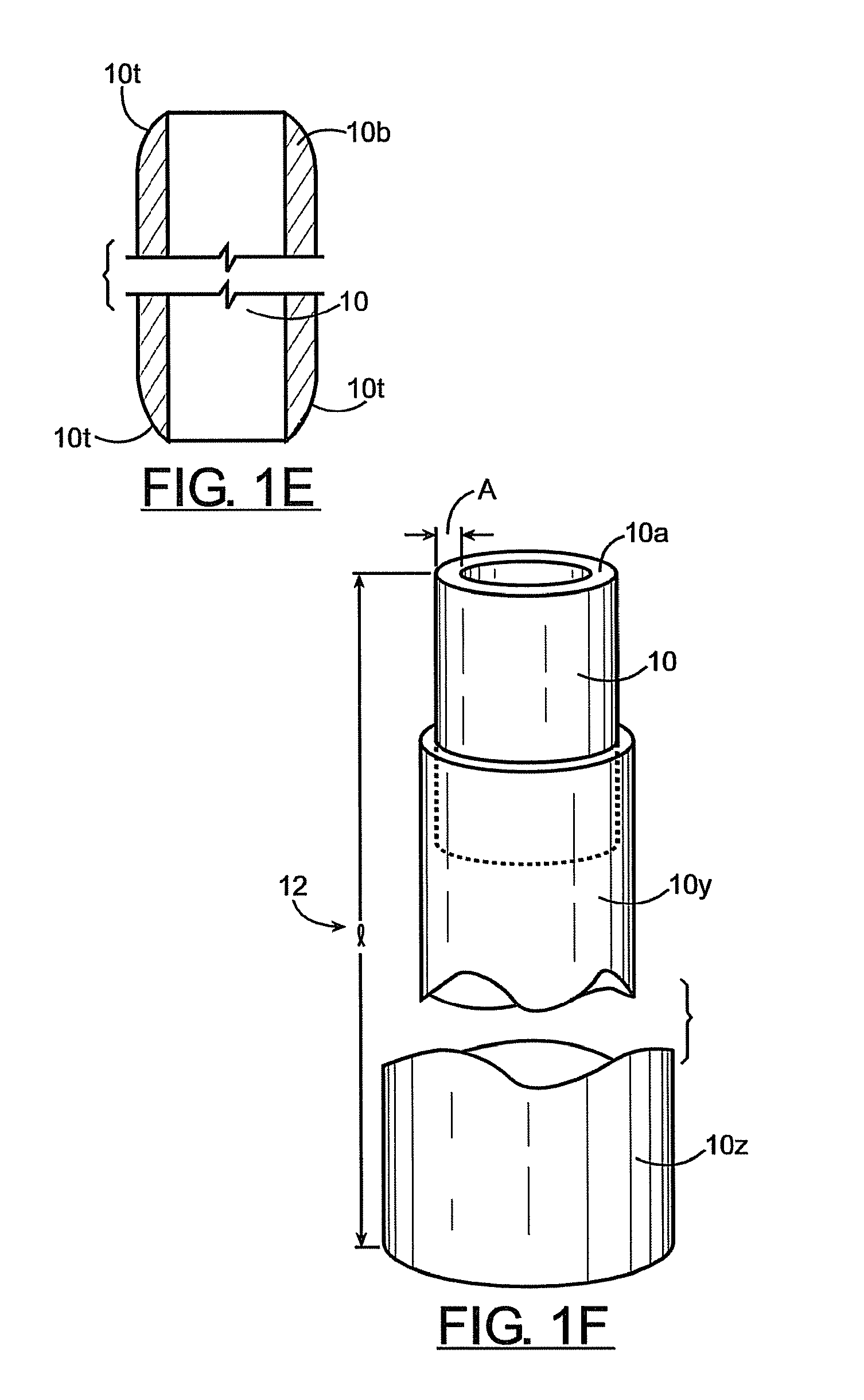
[0027]Referring to the drawings, specifically FIG. 1, a tube 10 of thermally responsive material, such as thermoplastics, is provided, having a length 12, an initial internal diameter 14 and an initial external diameter 16. The initial inner and outer diameters, 14, 16, of tube 10 define a tube thickness “A”. Tube 10, w...


PUM


Abstract

An expandable surgical retractor for minimally invasive surgical applications is disclosed. The expandable retractor, preferably in the form of an inflatable balloon retractor, is inserted in a surgical corridor and expanded to the desired size and shape. The retractor of the present invention is amenable to many shapes including cylindrical, conical with the base at the depth of the corridor, hourglass, and crescent and are dictated by the surgeon's needs. Cooling of the retractor allows the retractor to maintain the expanded characteristic. The expanded relatively rigid retractor provides an ideal corridor for surgical applications. In a preferred embodiment, a second retractor, of the invention, can be placed at a greater depth through the first placed retractor; the “telescoping” effect rapidly provides greater exposure with minimal manipulation. Following surgery, such retractor(s) can be removed in a manner that minimizes bleeding and tissue damage. One such method is reheating to soften and restore the retractor to its unexpanded size. Or, laterally placed perforations allow for fracturing of the retractor by bovie cautery, facilitating removal by “unzipping” the retractor.

Description

CROSS-REFERENCE TO RELATED APPLICATIONS[0001]This invention claims priority to U.S. Provisional Patent Application No. 60 / 824,234, titled “INFLATABLE SURGICAL RETRACTOR”, filed Aug. 31, 2006. The content of this] application is incorporated by reference into this application as if fully set forth herein.FIELD OF THE INVENTION[0002]The present invention concerns surgical devices used to maintain a surgical corridor. More particularly the present invention concerns a retractor created by materials having thermoplastic properties that permit the creation of a stable opening through which surgery can be performed.BACKGROUND OF THE INVENTION[0003]It is desirable when surgery is required, or in any medical procedures, to be as minimally invasive as possible. The well being of the patient and speed of recovery are often dependent on the degree to which a procedure is quickly and accurately accomplished, with as little damage to the body and with as little blood loss as possible. For this r...

Claims


Application Information

Patent Timeline
Patent Type & Authority Applications(United States)
IPC IPC(8): A61B1/32
CPCA61B2017/00557A61B17/0218
Inventor DESHMUKH, VIVEK R.CRAWFORD, NEIL R.
Owner DIGNITY HEALTH
Why Eureka
Try Eureka