Surgical tool for measurement of valve annulus and cusp geometry

a surgical tool and valve technology, applied in the field of cardiac surgery, can solve the problems of limited use of instruments, and achieve the effect of quick assessment of aortic structures or anatomic parameters

Active Publication Date: 2010-08-26
CORONEO
View PDF15 Cites 11 Cited by
  • Summary
  • Abstract
  • Description
  • Claims
  • Application Information

AI Technical Summary

Benefits of technology

[0009]Advantages of the present invention include that the proposed surgical tool, allows the surgeon with the insertion of one surgical tool in the aortic root, to quickly assess the aortic structures or anatomic parameters of the native aortic root complex including cusp structures. As such, these parameters can advantageously inform the surgeon of the extent of reconstruction required and suitable size of aortic implant that may be required to perform an effective reconstruction or replacement surgery.

Problems solved by technology

Such instruments are limited in their use in that they can only measure the internal diameter of the aortic root (schematically illustrated in FIG. 5, and labelled AA at the base of the aortic root and STJ at the level of the sinotubular junction).

Method used


Image

  • Surgical tool for measurement of valve annulus and cusp geometry
  • Surgical tool for measurement of valve annulus and cusp geometry
  • Surgical tool for measurement of valve annulus and cusp geometry

Examples


first embodiment

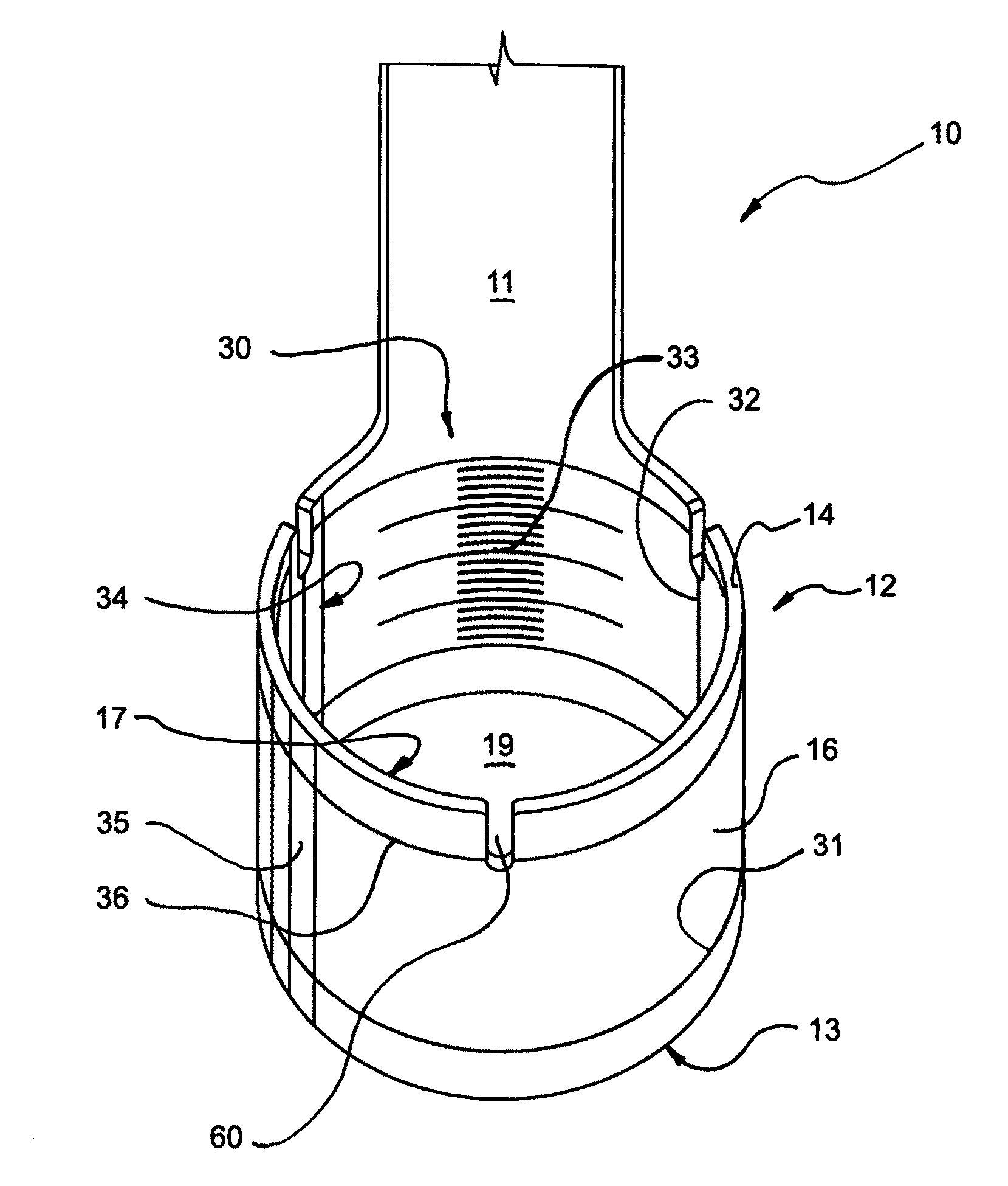
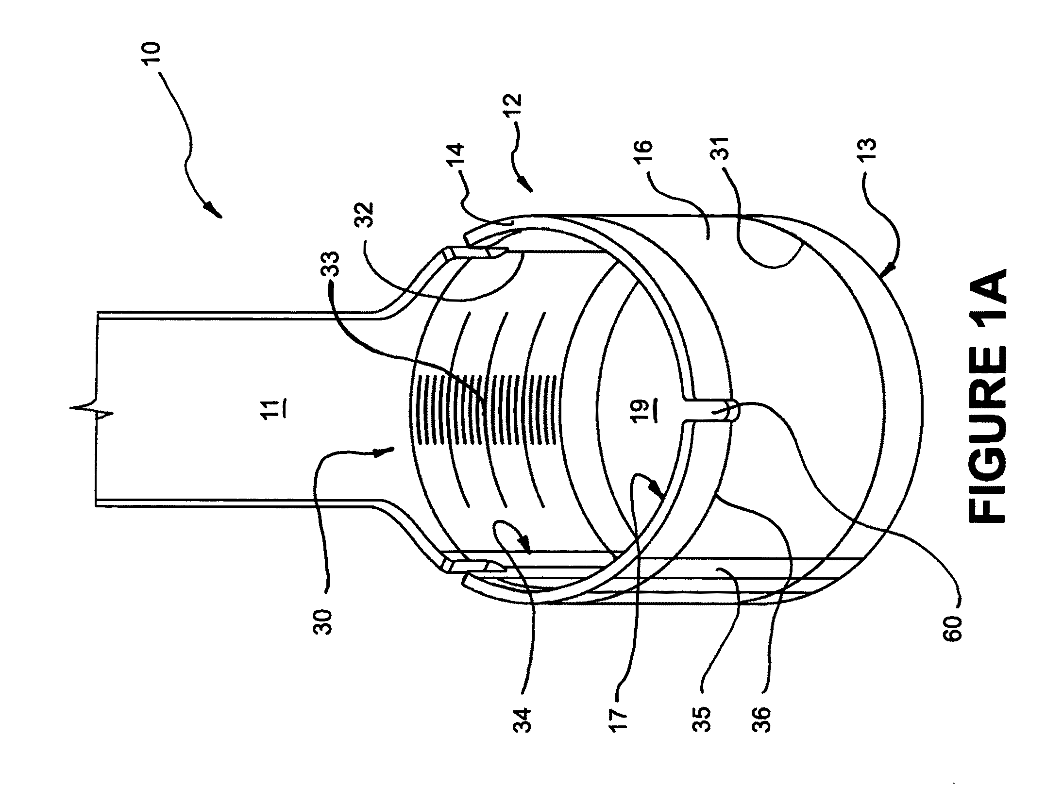
[0027]Referring to FIG. 1A, there is shown a surgical measuring tool, instrument or implement 10 in accordance with the present invention. Tool 10 is described here below and shown throughout the figures in the context of use during a repair an aortic valve 89 or reconstruction surgery of the aortic root 90. It should however be understood that tool 10 may be used in other surgical contexts where a cardiac valve is contained in a tubular conduit, without departing from the scope of the present invention. For example, surgical tool 10 may be used in the context of surgical repair of a pulmonary cardiac valve.

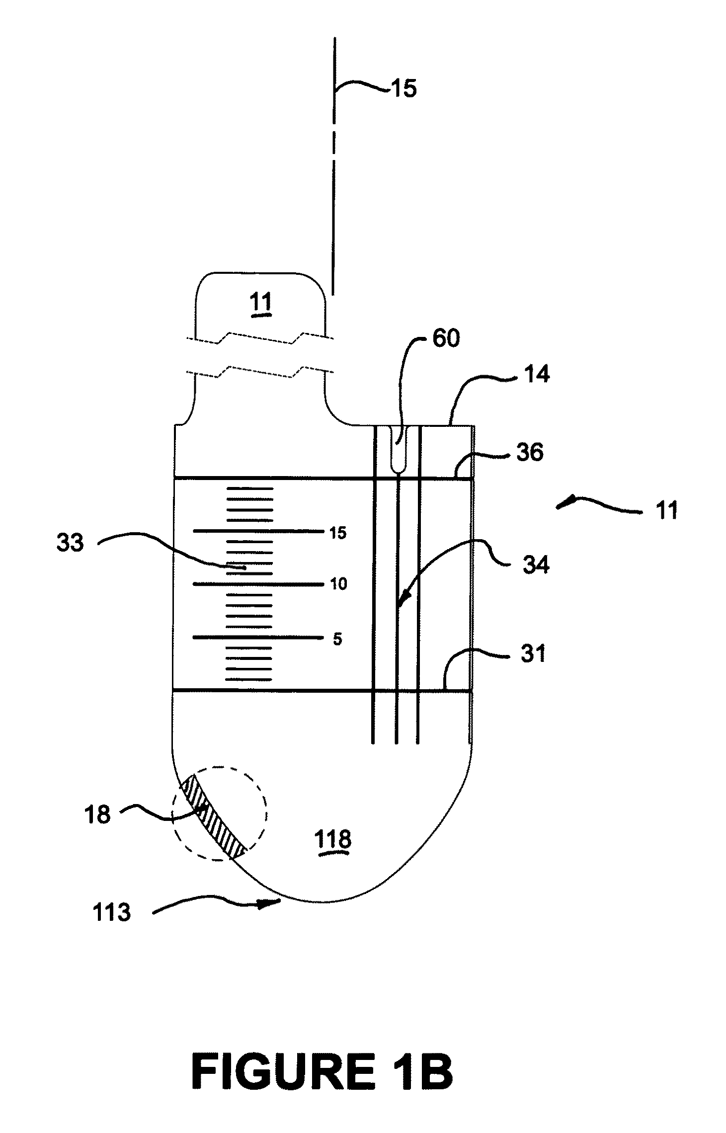
[0028]In a first embodiment, surgical measuring tool 10 is comprised of a handle portion 11 and a substantially cylindrical or tubular functional end or portion 12 configured and sized for insertion within an aortic root 90 of a patient's aorta 99. Functional end 12 is provided in a variety of calibrated external diametrical sizes to be able to measure the internal diameter of ao...

second embodiment

[0050]Referring now to FIGS. 7A-7C, the present invention will now be described in greater detail. Surgical tool 100 is comprised of a handle portion 11 and a substantially cylindrical portion 120. Handle portion 11 is either permanently mounted to top portion 140 of cylindrical portion 120, or demountable connected thereto so that a solitary handle may interchangeably be coupled to a variety of different incrementally sized cylindrical portions 120 so as to enable calibrated measurement of the internal diameter of the aortic root 90. Bottom portion 130 is configured with a progressively smaller diameter or profile to ease insertion into said aortic root. As illustrated, bottom portion 130 is configured with a substantially bullet shaped or parabolic profile 180. Other, progressively smaller profiles are also possible to ease insertion of measuring tool 100 into an aortic root, such as, for instance, a substantially conical or generally spherical or truncated conical profile. Top po...

third embodiment

[0052]Referring to FIGS. 8A-8B, the present invention will now be described in greater detail. Surgical tool 200 is similar to tool 100 except that it further comprises at least one optical lens member 170 for refracting the light reflected by conical mirror 153 a predetermined amount. In this embodiment, optical lens 170 is of a generally concave geometry. Tool 200 requires at least one lens member, but depending on the amount of refraction desired or optical manipulation sought, a pair, or even a plurality of cooperating lens members may be advantageously used.

[0053]With reference to FIG. 8B, optical lens 170 refracts light by a predetermined amount in a manner that reduces the magnification of the aortic structures being reflected by conical mirror 153, refracted by lens 170 and visible on top portion 140. As such, measurement increments 332 in reflected measurement array 302 are closer together than the measurement increments 33 in the array 30. As well, the aortic structures in...


PUM


Abstract

A surgical tool for visually assessing or measuring the aortic structures contained within a generally tubular aortic root. The surgical tool is appropriately configured and sized to be insertable within an aortic root during surgery. The surgical tool comprises a handle portion and a cylindrical portion connectable thereto. The cylindrical portion defines an external cylindrical surface and extends in height along a tool axis between a base portion and a top portion. The cylindrical portion being optically clear or having at least a section thereof that is sufficiently transparent whereby, in use, when the surgical tool is placed within the aortic root and the aortic structures are in contact with the external cylindrical surface, the aortic structures are visible through said optically clear or sufficiently transparent section. The cylindrical portion preferably further comprises an array of reference datum and measurement increments visible through the optically clear section such that the visualization and measurement of the aortic structures may be effected with reference to the array.

Description

[0001]This application claims the benefits of U.S. Provisional Patent Application 61 / 193,663 filed Dec. 15, 2008.FIELD OF THE INVENTION[0002]The present invention relates to the field of cardiac surgery, and more specifically to the field of surgical instruments used in cardiac valve surgery or reconstructive surgery of the aorta.BACKGROUND OF THE INVENTION[0003]The mammalian heart is an organ made up of four muscular chambers that function together to pump blood throughout the body. Each of the four chambers has an associated downstream one-way valve made up of movable, coapting leaflets or cusps which cooperate to prevent the backward flow of blood, or regurgitation, into their respective chambers. Two such heart valves, the aortic and pulmonary valves, also commonly known as the semilunar valves, are characterized by three leaflets or cusps 91. The aortic valve leaflets 91 are attached within the aortic root 90, usually to a tri-scalloped or triple scalloped line of collagenous, ...

Claims


Application Information

Patent Timeline
Patent Type & Authority Applications(United States)
IPC IPC(8): A61B1/32
CPCA61B5/1076A61B19/46A61B2017/00907A61F2/2496A61F2/2415A61F2250/0097A61B2019/461A61B90/06A61B2090/061
Inventor PAOLITTO, ANTHONYPAQUETTE, JONATHANVALENTINI, VALERIO
Owner CORONEO
Why Eureka
Try Eureka