
Active Medical Implant

a technology of active medical implants and implants, applied in the field of active medical implants, can solve the problems of not being able to achieve large-scale medical practice, energy storage mechanism depletion, replacement or recharge, etc., and achieve the effect of eliminating the thermal burden on the tissue in charging and prolonging life expectancy

Active Publication Date: 2010-08-26
BIOTRONIK SE & CO KG
View PDF16 Cites 9 Cited by
  • Summary
  • Abstract
  • Description
  • Claims
  • Application Information

AI Technical Summary

Benefits of technology

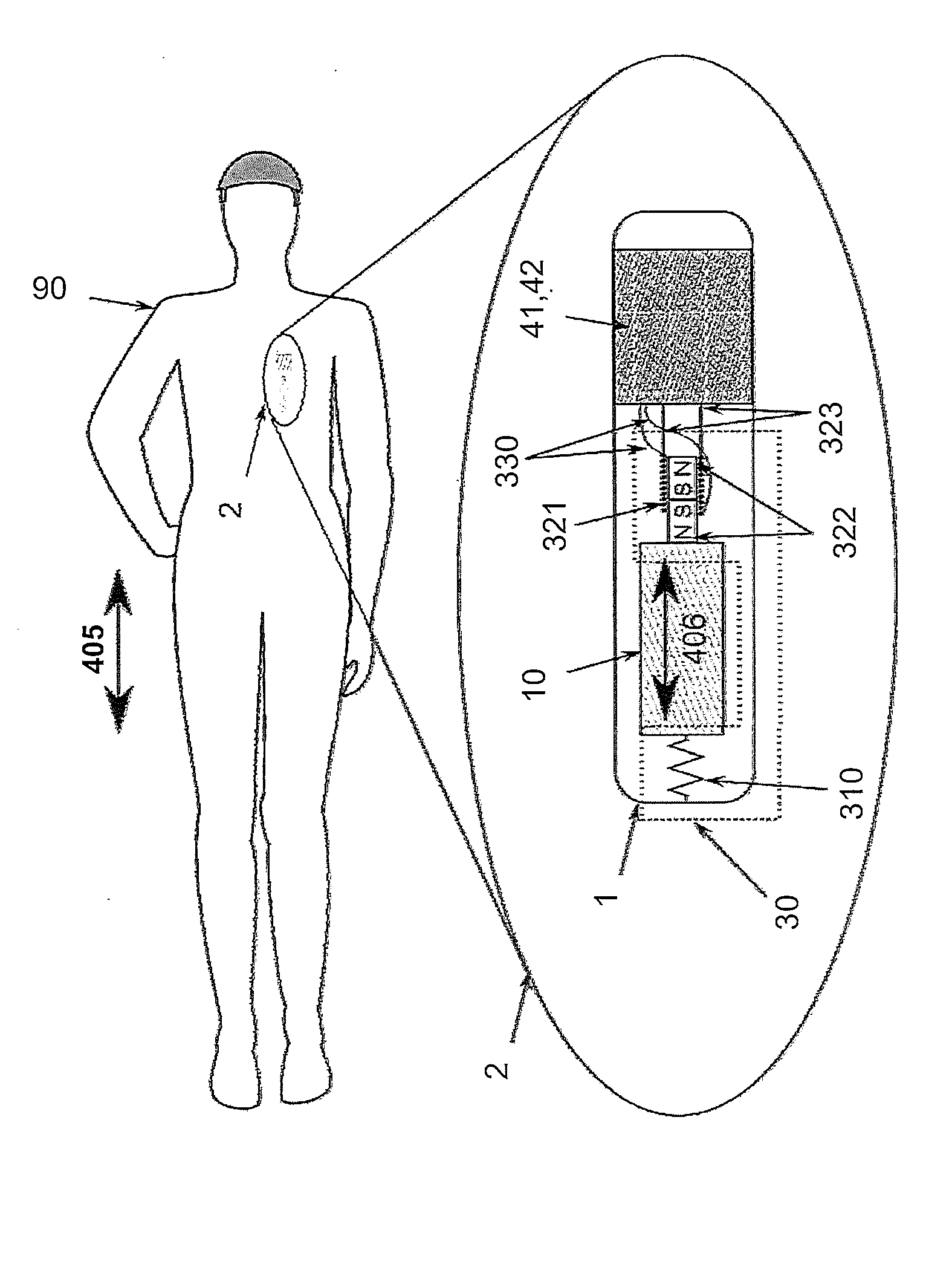
[0011]It is possible to provide for the vibrator or rotor to be arranged in a shared housing together with the active electric components of the implant. However, the vibration-capable system may also be implanted as a separate IMD outside of the active implant, and the power may be transmitted to the electronic system of the active implant. In this way, the vibration-capable system can be attached closer to a bone, for example, and can be better linked to high-energy movements of the body.
[0015]The mass of the vibrator may thus be increased and the natural frequency may be reduced. This may go so far that the vibration-capable system is formed by the entire internal structure of the implant (energy storage mechanism, electric circuit, mounting frame, etc.).
[0020]construction of implants having a longer life expectancy than in the past, without the implant having to rely on regular charging operations from the outside. This also eliminates the thermal burden on the tissue in charging (e.g., due to eddy currents in the metallic housing, which are induced by an alternating magnetic field).

Problems solved by technology

A transcutaneous power supply can be used for only short periods of time because there is a high risk of infection or the constant HF burden can lead to tissue damage.
Therefore, this has not been successful in medical practice on a large scale.
Energy storage mechanisms become depleted after a certain amount of time and must be replaced or recharged.
In the past, this was the most common procedure, but it is complicated, expensive and associated with medical risks and considerable discomfort for the user of the implant.
A charging cycle of the energy storage mechanism may also become very long due to the low energy transfer rate.
Depending on the use of the transcutaneous energy transfer, the rechargeable cell may become very highly discharged before the charging operation, thus reducing the lifetime of the cell.
In the physician's practice, it requires a great deal of organizational effort and discipline on the part of the patient but this is often not adequately ensured in practice.

Method used


Image

  • Active Medical Implant
  • Active Medical Implant
  • Active Medical Implant

Examples


Embodiment Construction

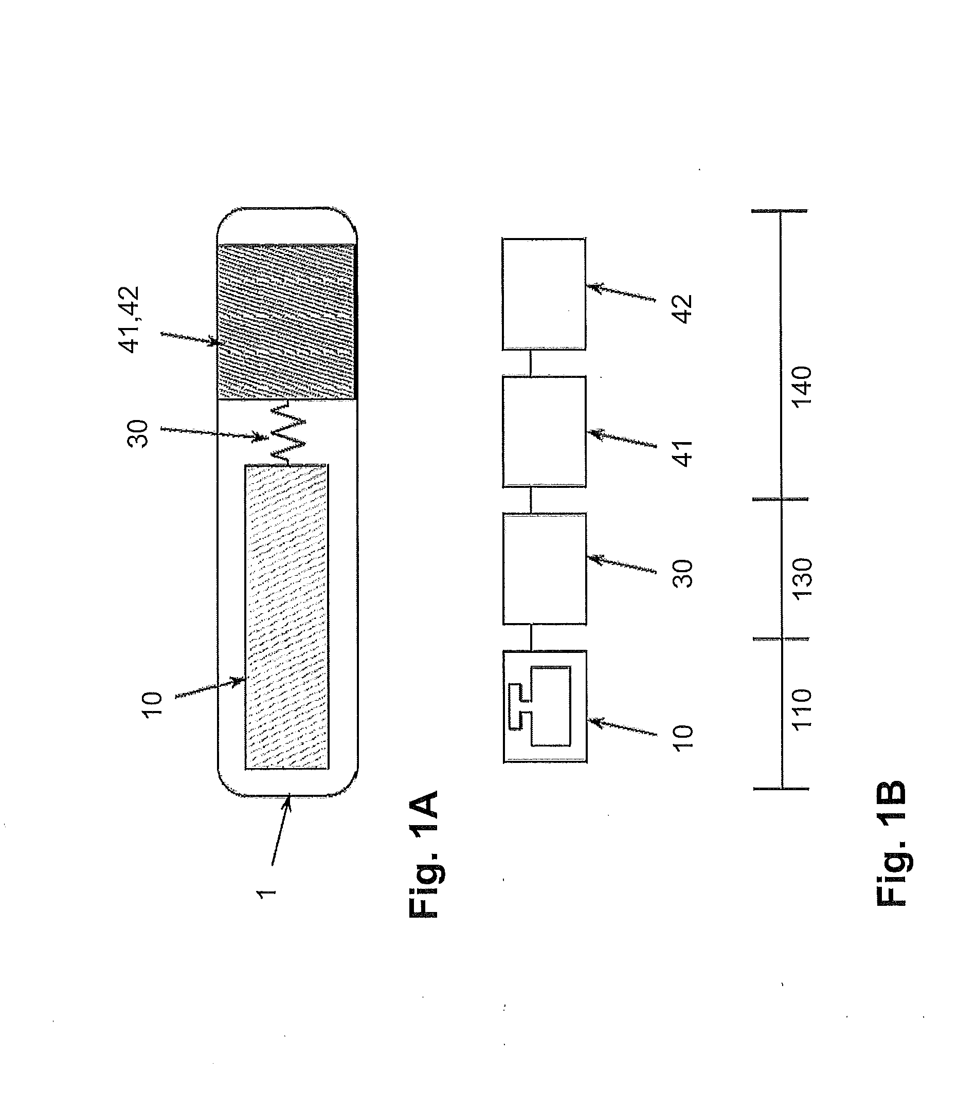
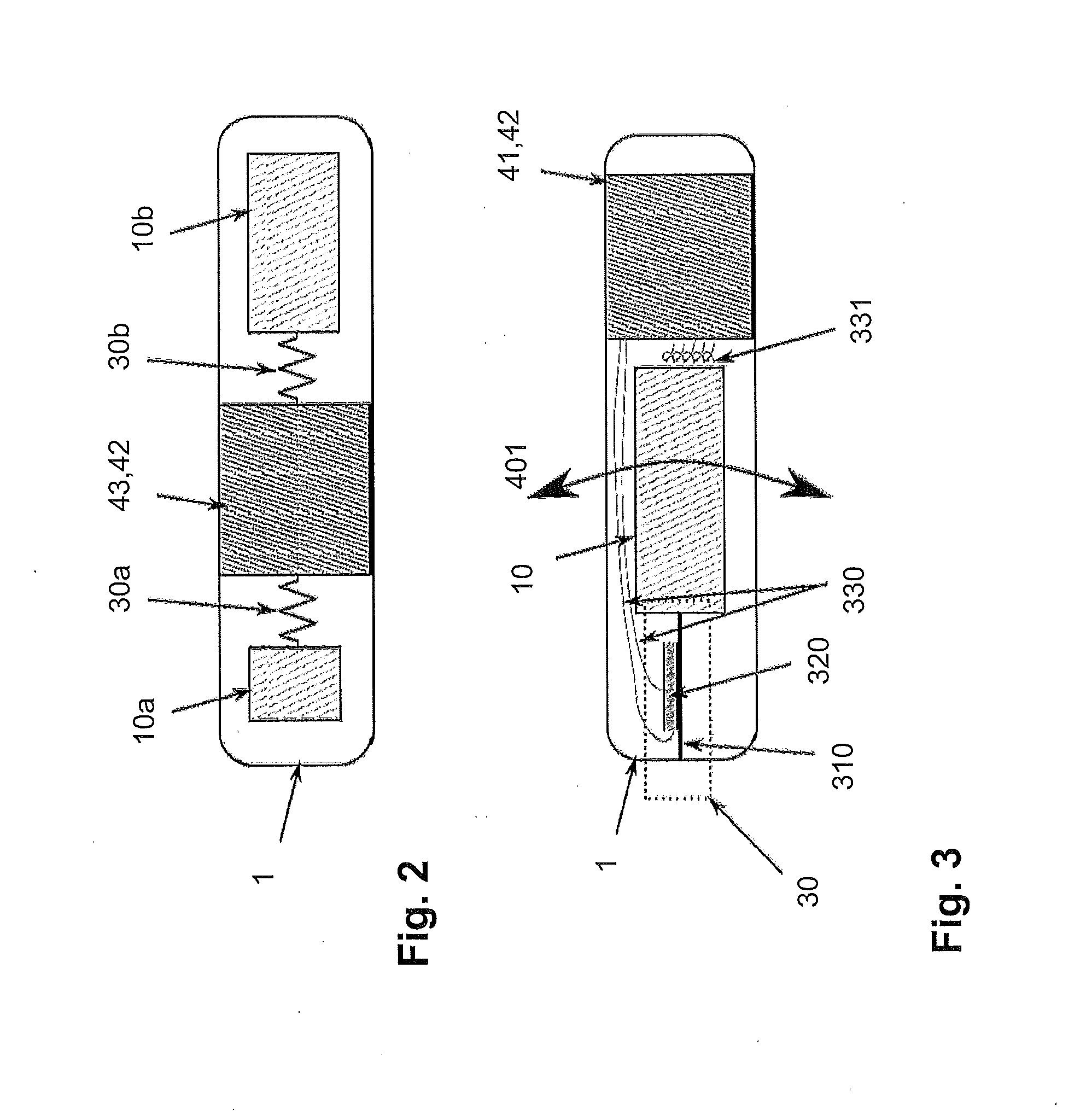
[0034]FIG. 1A shows an active implant 1 having a housing 1a, which holds a movable component mass 10. The mass 10 is connected to additional components 41, 42 fixedly installed in the housing or connected to the housing 1a itself via a coupling system 30. The coupling system converts the energy of mechanical vibration into electricity and makes this power available to the implant electronic system 41. The energy may be stored in a power reservoir 42. This reservoir may be an electrochemical cell or a capacitor.

[0035]The system illustrated in FIG. 1B may be described physically by a vibration-capable mass 10 coupled to a mechanical-electric converter 30, an electric circuit 41 and a power reservoir 42. In the first section of the system, the mass may execute movements. The energy of the movements is converted into electricity by the mechanical-electric converter in the second portion 130. In the last portion 140, electricity is utilized by the implant electronic system 41 and / or stor...


PUM


Abstract

An active medical implant, in particular a medical electronic device having a power supply which has a mechanical vibrator or rotor which is induced to vibrate and / or rotate by movements of the patient wearing the implant and / or external excitation and is energetically connected to an electronic consumer and / or an energy storage mechanism, such that a portion of the kinetic energy generated by the vibration and / or rotation is input into the consumer and / or energy storage mechanism.

Description

CROSS-REFERENCE TO RELATED APPLICATIONS[0001]This application claims the priority of German Patent Application No. DE 10 2009 001 042.4, filed on Feb. 20, 2009 in the German Patent Office, the disclosure of which is incorporated herein in its entirety by reference.FIELD OF THE INVENTION[0002]The invention relates to an active medical implant, in particular a medical electronic device such as a cardiac pacemaker, an implantable defibrillator, an implantable medication dosing pump or a similar device.BACKGROUND OF THE INVENTION[0003]For their power supply, active medical implants either have an energy storage mechanism (battery, capacitor) or are constantly supplied with power transcutaneously (via cable, HF, alternating magnetic field). A transcutaneous power supply can be used for only short periods of time because there is a high risk of infection or the constant HF burden can lead to tissue damage. Therefore, this has not been successful in medical practice on a large scale.[0004]...

Claims


Application Information

Patent Timeline
IPC IPC(8): A61N1/378
CPCA61N1/3785
Inventor WEISS, INGOKNORR, STEFAN
Owner BIOTRONIK SE & CO KG
Learn More