

Diagnostic connector assembly (DCA) interface unit (DIU)
a technology of connector assembly and interface unit, which is applied in the direction of vehicle testing, structural/machine measurement, instruments, etc., can solve the problems of increasing the logistical footprint, not providing constant operation concept, and only effective special test equipment used in the pas
- Summary
- Abstract
- Description
- Claims
- Application Information
AI Technical Summary
Benefits of technology
Problems solved by technology
Method used
Image

Examples
Embodiment Construction
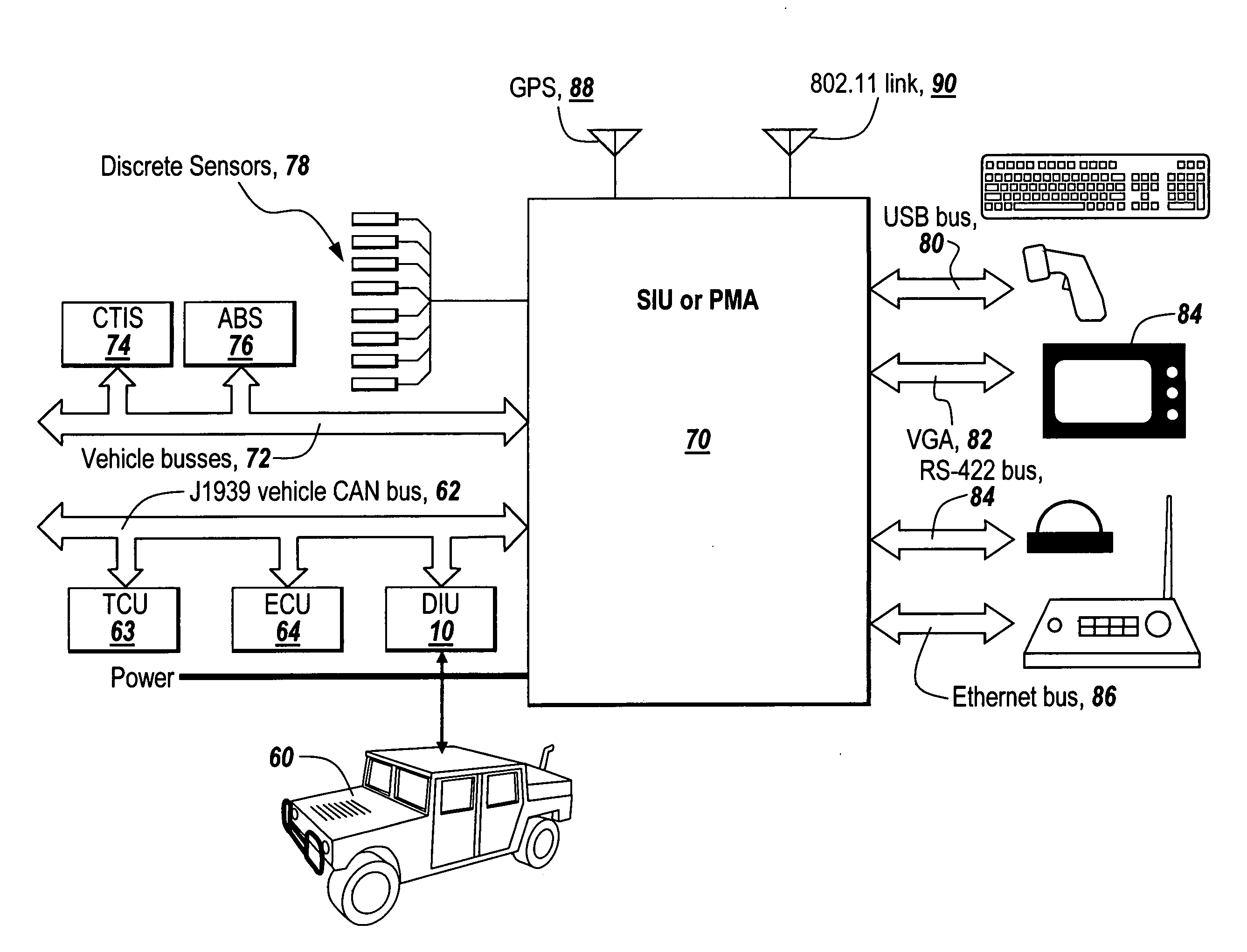
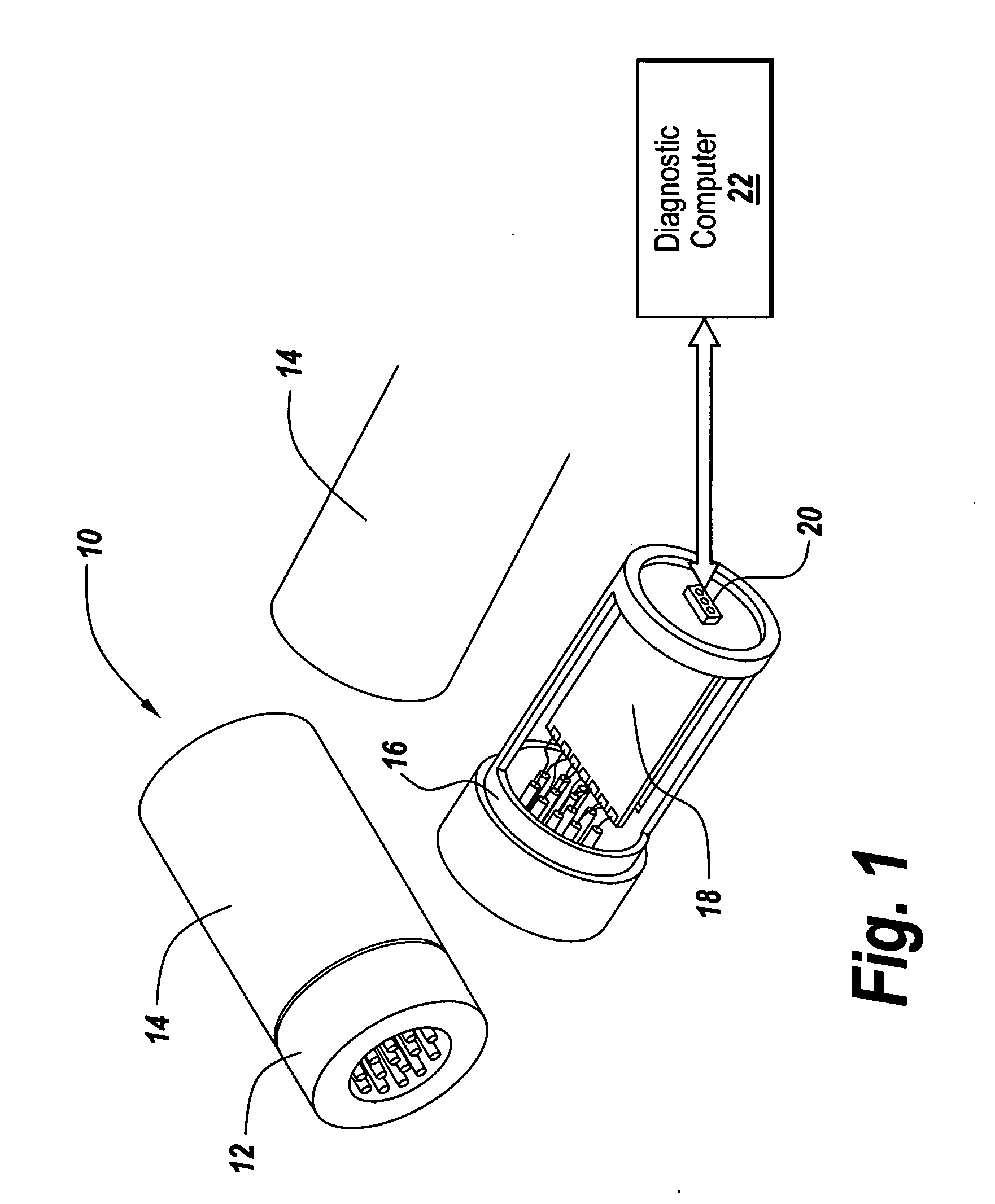
[0029]Referring to FIG. 1, a diagnostic connector assembly in the form of a diagnostic interface unit 10 eliminates the need for special test equipment while providing constant, real time monitoring. Diagnostic interface unit 10 includes a vehicle connector assembly 12 at one end of an outer cylindrical housing 14. Housing 14 slips over an inner cylindrical housing 16 that is apertured to expose a printed circuit board assembly 18 having contact pads connected to the connectors of connector assembly 12. An RS-422 or like connector 20 is used to connect the output of board 18 to a diagnostic computer 22.
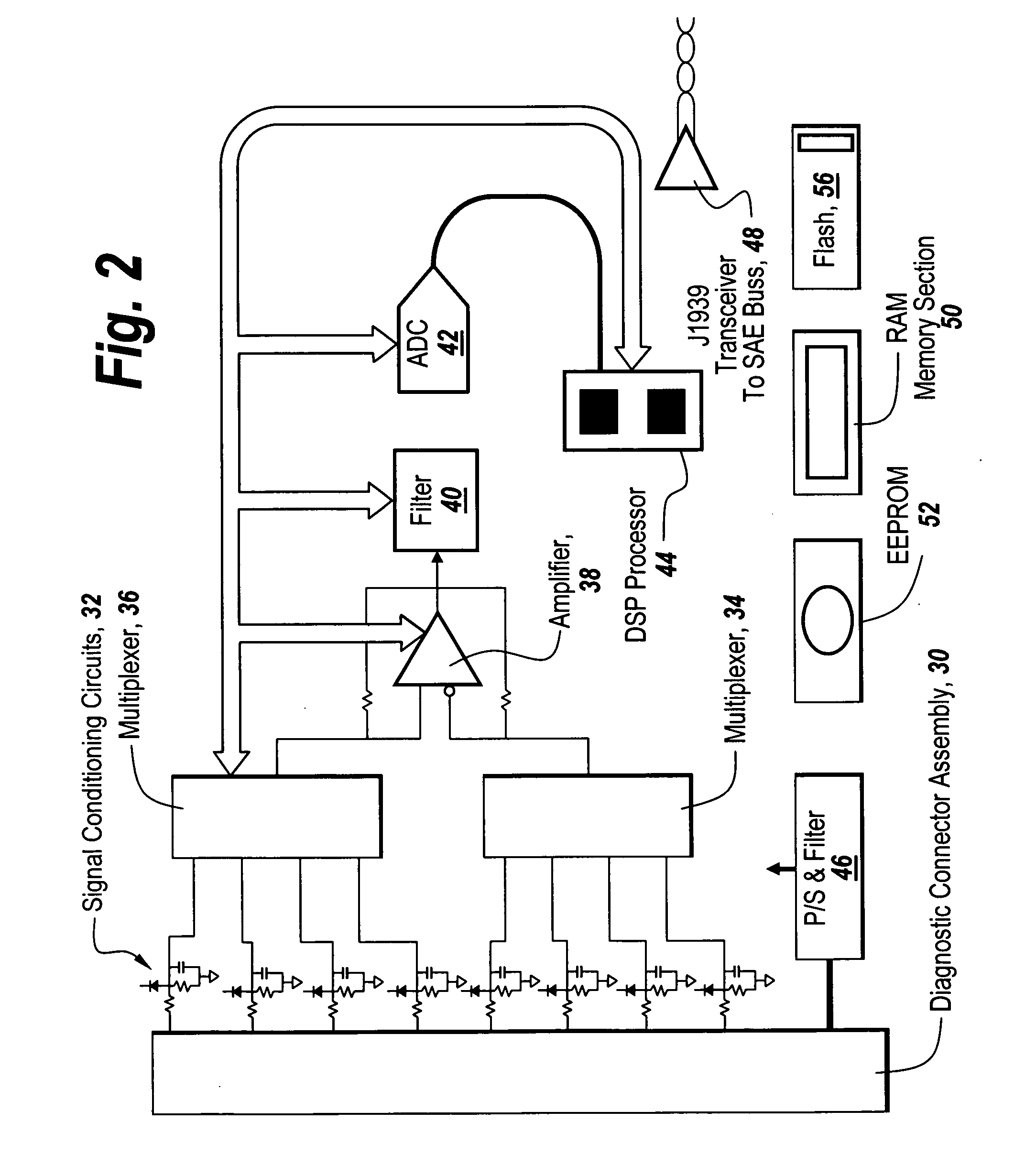
[0030]The diagnostic interface unit approximates a modern engine sensing unit, and is adapted to be permanently installed on vehicles to provide constant engine status that allows health and status awareness, as well as, interactive diagnostics and prognostics. The diagnostic interface unit provides an analog interface with signal conditioning and switching, a digitizer with an analog...
PUM
 Abstract
Description
Claims
Application Information