System and method for cooling rocket engines

a rocket engine and cooling system technology, applied in the field of rocket engine cooling system, can solve the problems of insufficient surface tension device for no currently developed diaphragm tank technology for liquid oxygen, and no current demonstration of nitrous oxide and liquid oxygen surface tension devi

Active Publication Date: 2010-09-02
XCOR AEROSPACE
View PDF9 Cites 22 Cited by
  • Summary
  • Abstract
  • Description
  • Claims
  • Application Information

AI Technical Summary

Problems solved by technology

Nitrogen tetroxide and hydrazine are toxic and environmentally hazardous.
Other propellants, such as nitrous oxide (N2O) and liquid oxygen (O2) combined with a variety of fuels do not have these drawbacks, but there is no currently developed diaphragm tank technology for liquid oxygen and surface tension devices for nitrous oxide and liquid oxygen have not yet been demonstrated.
Furthermore, surface-tension devices only operate in extremely low gravity environments, and many vehicles require a propellant feed solution which works under a range of acceleration environments and directions.
Self-pressurized propellant by itself does not provide zero-gravity feed; however it is possible to consistently feed the gaseous form of the propellant out of the propellant tank by means of a heat exchanger between the withdrawn propellant and the tank contents.
Ho

Method used


Image

  • System and method for cooling rocket engines
  • System and method for cooling rocket engines
  • System and method for cooling rocket engines

Examples


Embodiment Construction

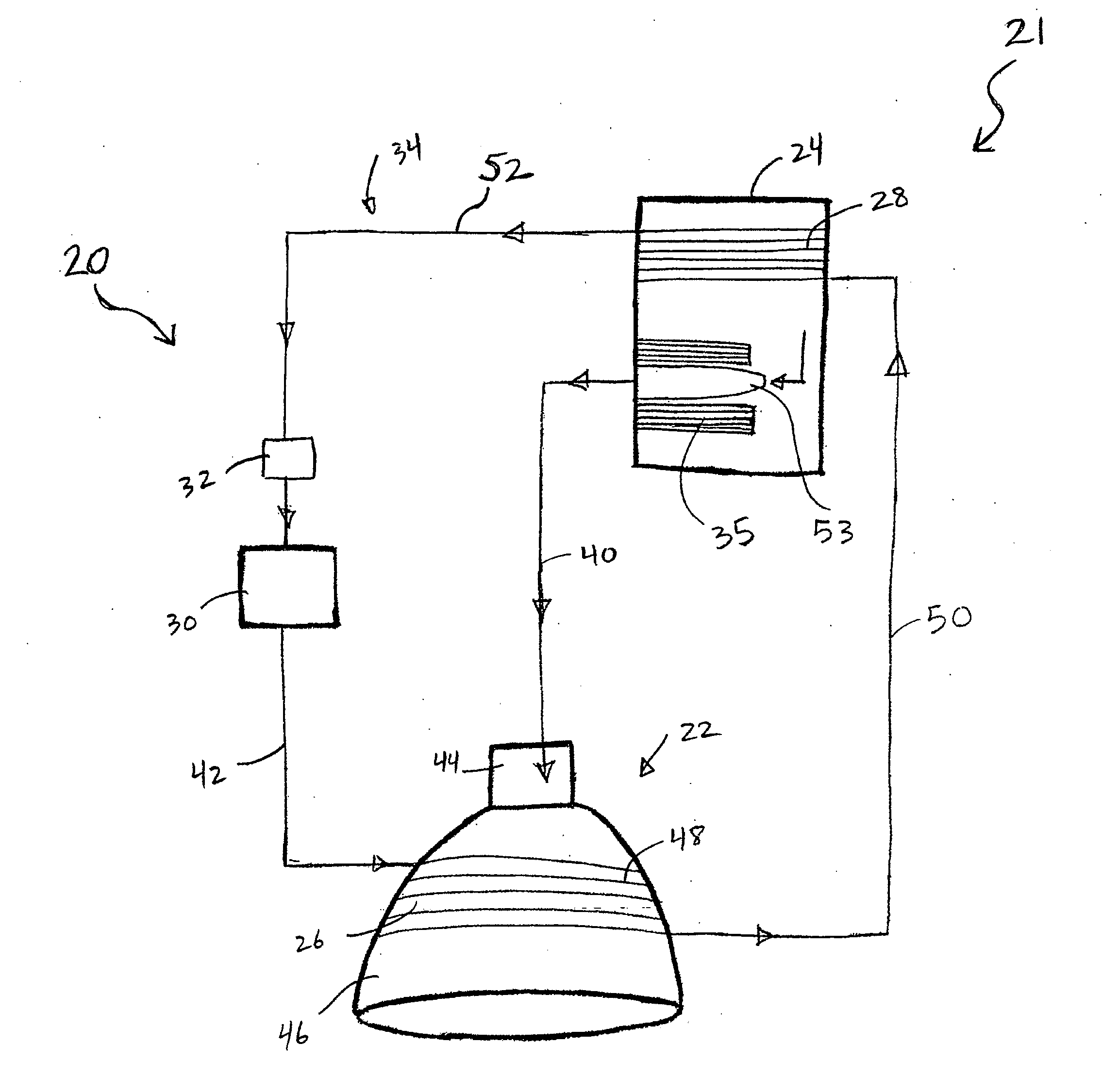
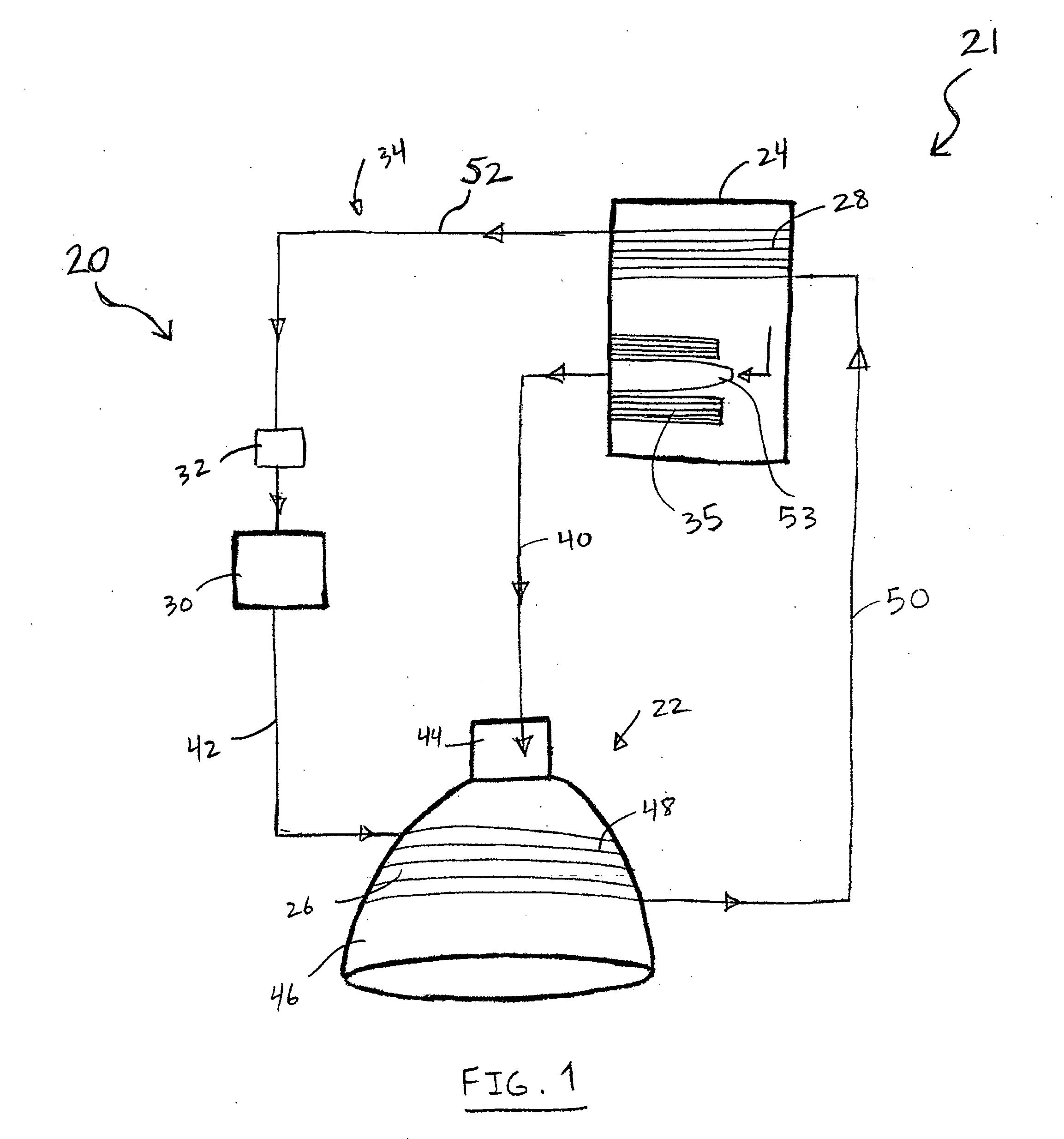
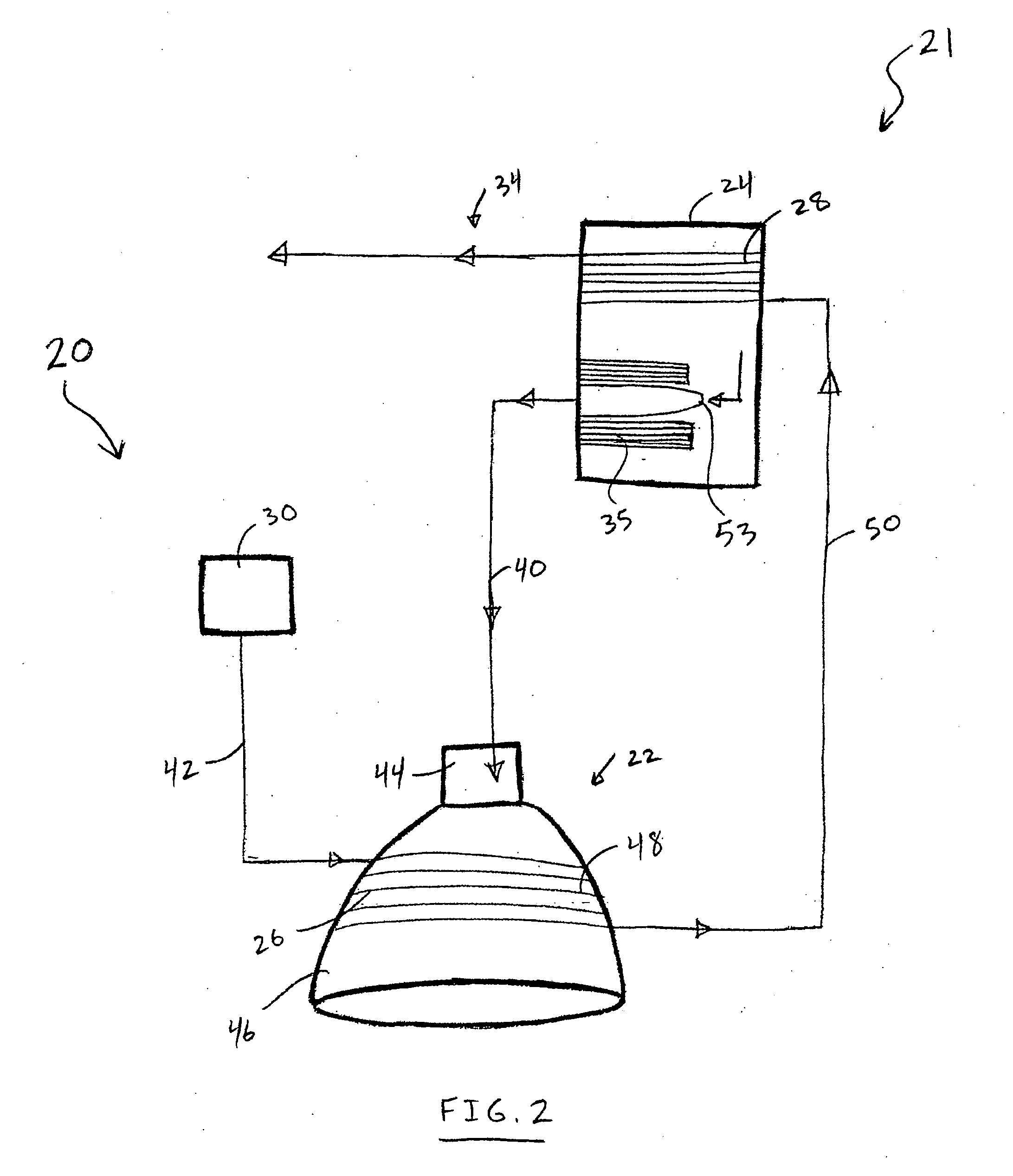
[0018]Referring to FIGS. 1-6, a cooling system 20 constructed in accordance with the teachings of the present disclosure for a propulsion system 21 is shown. The propulsion system 21 includes a rocket engine 22 and one or more propellant tanks 24, which can be in fluid communication with the rocket engine 22 to supply a propellant to the rocket engine 22 for combustion. In FIGS. 1-6, a monopropellant propulsion system is shown with only one propellant tank 24. In FIG. 7, a bipropellant propulsion system is shown having two propellant tanks 24. Accordingly, the present disclosure is applicable to any rocket engine regardless of the number and configuration of propellant tanks and oxidizer tanks used. The propulsion system 21 may also include a first heat exchanger 26 that is thermally coupled to the rocket engine 22. The cooling system 20 includes a second heat exchanger 28 that is thermally coupled to the propellant tank 24, and a coolant tank 30 configured to hold a coolant. The fi...


PUM


Abstract

A propulsion system for a rocket engine and a method of cooling a rocket engine includes a propellant tank fluidically coupled to the rocket engine to hold a pressurized propellant, a coolant tank to hold a coolant, a first heat exchanger thermally coupled to the rocket engine and fluidically coupled to the coolant tank, a second heat exchanger thermally coupled to the propellant tank and fluidically coupled to the first heat exchanger, and a third heat exchanger disposed inside the propellant tank to thermally couple a propellant withdrawn from the tank for combustion to a propellant disposed inside the tank. The coolant flows from the coolant tank to the first heat exchanger and through the first heat exchanger to cool the rocket engine. The propellant withdrawn from the propellant tank receives heat from the propellant disposed inside the tank through the third heat exchanger to convert to a gaseous propellant when withdrawn from the propellant tank as a liquid propellant. The coolant flows from the first heat exchanger to the second heat exchanger and through the second heat exchanger to heat the propellant disposed inside the propellant tank.

Description

FIELD OF THE DISCLOSURE[0001]The present disclosure generally relates to rocket engines, and more particularly, to a cooling system for rocket engines.BACKGROUND[0002]Rocket engines are used for missiles, for launching space bound vehicles, and control of spacecraft in space. Rocket engines that are used to control the attitude of a spacecraft in space are generally referred to as thrusters. Firing a thruster produces a propulsive force that is opposite to the direction of the combustion gases exiting the nozzle of the thruster. The duration of firing and the timing of firing of multiple thrusters can be adjusted to impart sufficient torque on the spacecraft to obtain the desired attitude of the spacecraft. Thus, multiple thrusters are rapidly and repeatedly fired for accurate control of spacecraft attitude.[0003]Thrusters typically use liquid monopropellants such as hydrogen peroxide (H2O2) or hydrazine (N2H4), or room temperature storable bipropellants such as nitrogen tetroxide (...

Claims


Application Information

Patent Timeline
IPC IPC(8): F02K9/00F28D15/00
CPCF02K9/64
Inventor GREASON, JEFFREY K.DELONG, DANIEL L.JONES, DOUGLAS B.
Owner XCOR AEROSPACE
Why Eureka
Try Eureka