
Passive heat engine systems and components

a passive heat engine and heat pump technology, applied in the direction of machines/engines, indirect heat exchangers, lighting and heating apparatus, etc., can solve the problems of high maintenance costs of heat transfer pumps and systems, inefficient extraction of heat from various sources, and parasitic losses

Inactive Publication Date: 2010-09-02
MILES MARK W
View PDF18 Cites 31 Cited by
  • Summary
  • Abstract
  • Description
  • Claims
  • Application Information

AI Technical Summary

Benefits of technology

[0019]In accordance with a fifth embodiment of the invention, there is provided a heat engine system, comprising: a heat engine, comprising a working fluid circulati...

Problems solved by technology

Parasitic losses in the form of power required by pumps to circulate heat transfer fluids within a piping system.
High maintenance costs of heat transfer pumps and systems.
Inefficient extraction of heat from the various sources.
Heat losses from the heat extraction components.
Excessive size of heat exchange units due to inefficient heat exchangers.
Excessive size of heat rejection unit due to inefficient heat exchangers.
Inefficiencies in the transfer of heat to and from the working fluid.
Negative environmental impacts associated with extracting and rejecting heat to and from natural sources.
High cost and complexity of systems to extract and reject heat to and from environmental sources.

Method used


Image

  • Passive heat engine systems and components
  • Passive heat engine systems and components
  • Passive heat engine systems and components

Examples


Embodiment Construction

[0043]In the following description, for purposes of explanation, numerous specific details are set forth in order to provide a thorough understanding of the invention. It will be apparent, however, to one skilled in the art that the invention can be practiced without these specific details.

[0044]Reference in this specification to “one embodiment” or “an embodiment” means that a particular feature, structure, or characteristic described in connection with the embodiment is included in at least one embodiment of the invention. The appearances of the phrase “in one embodiment” in various places in the specification are not necessarily all referring to the same embodiment, nor are separate or alternative embodiments mutually exclusive of other embodiments. Moreover, various features are described which may be exhibited by some embodiments and not by others. Similarly, various requirements are described which may be requirements for some embodiments but not other embodiments.

[0045]In one...


PUM


Abstract

Methods for harnessing a heat source to produce energy are provided. One method comprises transferring heat from the heat source to a working fluid using at least one heat pipe; and performing work via the heated working fluid. Another method comprises operating a thermodynamic cycle to convert heat into work, comprising displacing a working fluid within a closed loop, said closed loop being defined by a first pathway within a working chamber, and a return pathway external to the return chamber; wherein displacement of the working fluid along the first pathway causes sympathetic displaced of a movable member held captive in the working chamber, and displacement of the working fluid along the external pathway is under influence of capillary forces; and transferring heat to the working fluid using at least one first heat pipe. Components and systems for implementing the methods are also provided.

Description

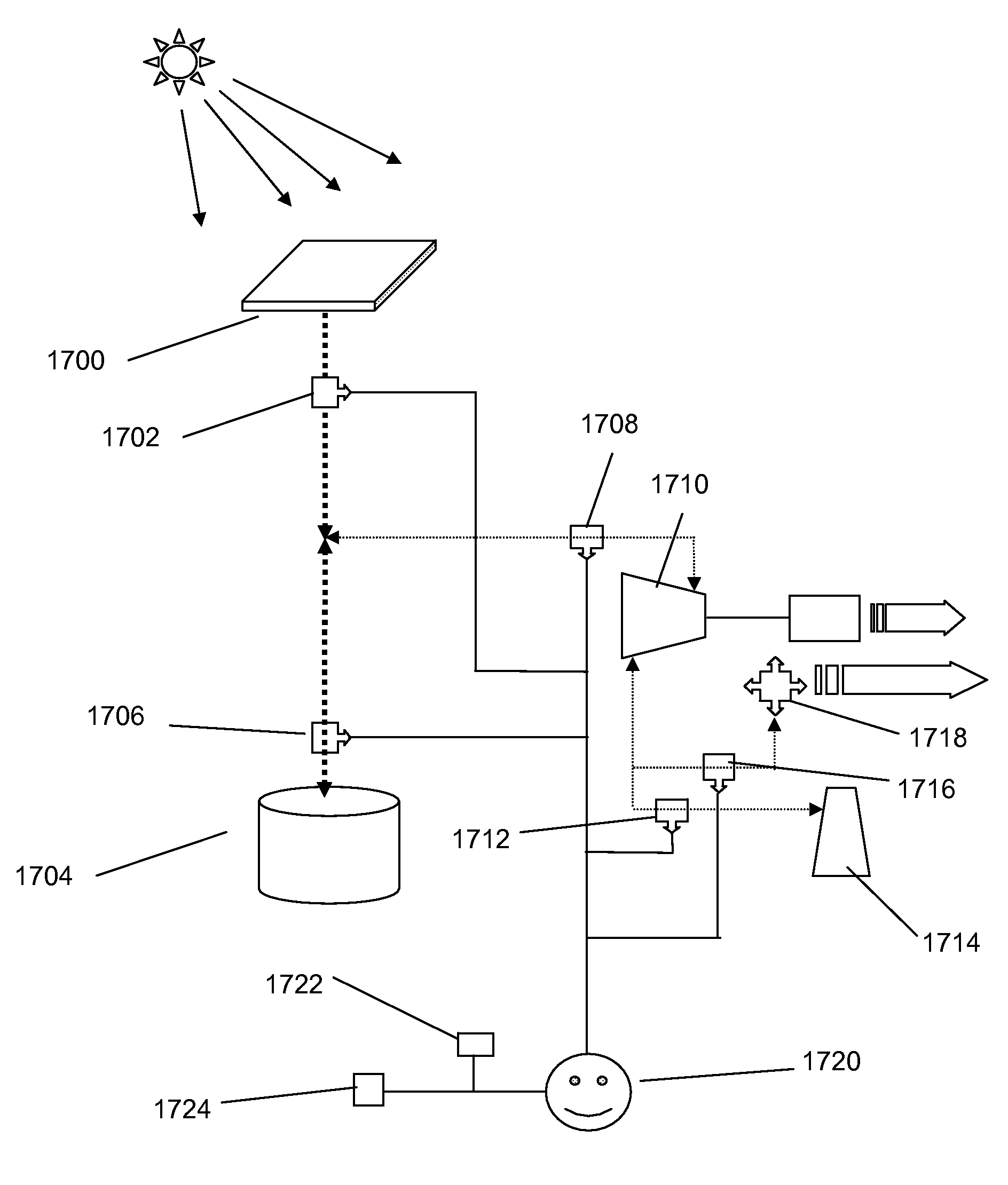
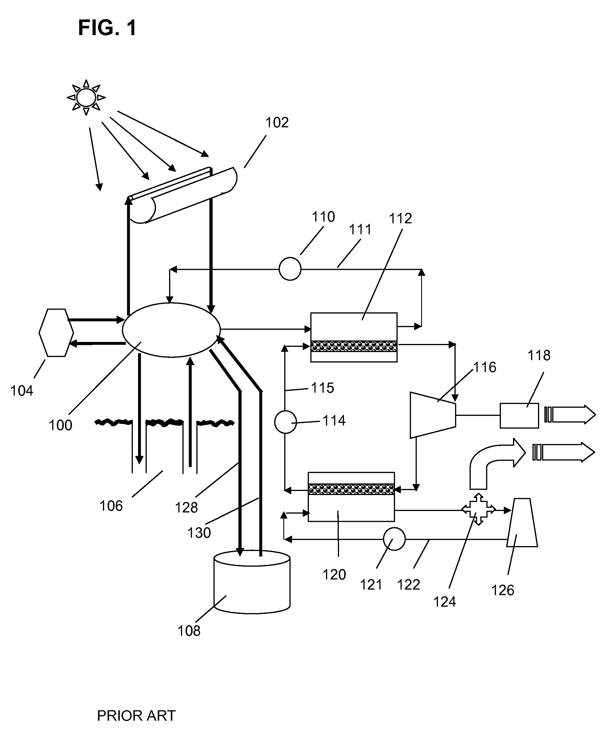
FIELD[0001]Embodiments of the present invention relate to heat engine systems.BACKGROUND[0002]FIG. 1 is a schematic illustration of a heat engine system which is supplied with heat from generic source 100. Generic heat source 100 represents a variety of heat sources including but not limited to sources 102, 104, and 106, representing solar, combustion, and geothermal sources, respectively. In one embodiment, pump 110 extracts heat from the source by pumping a heat transfer fluid (such as water) through piping system 111. The heat is transferred via heat exchanger 112, to a working fluid (such as water, a refrigerant, or other liquid medium) which is circulated via pump 114 via working fluid piping system 115.[0003]The working fluid is heated in the heat exchanger and is consequently turned into a vapor which drives turbine 116. Turbine 116 is mechanically connected to electric generator 118, resulting in the production of electricity. Heat exchanger 120 serves to cool the working fl...

Claims


Application Information

Patent Timeline
IPC IPC(8): F02G1/053
CPCF02G1/055F02G2254/20F24J2/32F24J3/086F28F13/003Y02E60/142F28D15/0275F28D20/00Y02E10/44Y02E10/16F28D15/0233F24T10/30Y02E10/10F24T10/40F24S10/95Y02E60/14Y02E10/40
Inventor MILES, MARK W.
Owner MILES MARK W
Learn More