Process line control apparatus and method for controlling process line

a technology of process line and control apparatus, which is applied in the direction of heat treatment apparatus, lighting and heating apparatus, furniture, etc., can solve the problems of high noise and difficulty in the current techniques to measure the crystal grain size of steel materials moving at such a high speed, and achieve the effect of improving the quality of steel materials

Inactive Publication Date: 2010-09-02
TOSHIBA MITSUBISHI-ELECTRIC IND SYST CORP
View PDF3 Cites 48 Cited by
  • Summary
  • Abstract
  • Description
  • Claims
  • Application Information

AI Technical Summary

Benefits of technology

[0019]Thus, an object of the present invention is to provide an apparatus and method for controlling a process line which can improve the quality of a steel material.

Problems solved by technology

However, the method shown in Patent Document 5 has the following problems.
It is difficult for the current techniques to measure the crystal grain size of a steel material moving at such a high speed.
High-frequency vibration may occur during high-speed movement, resulting in much noise.

Method used


Image

  • Process line control apparatus and method for controlling process line
  • Process line control apparatus and method for controlling process line
  • Process line control apparatus and method for controlling process line

Examples


first embodiment

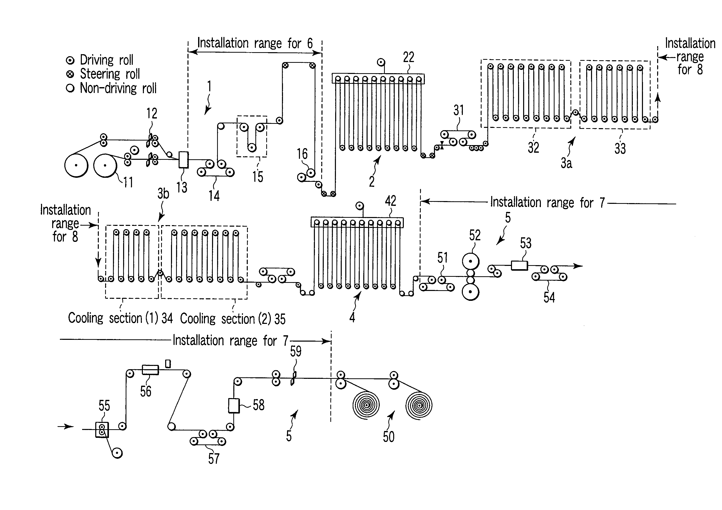
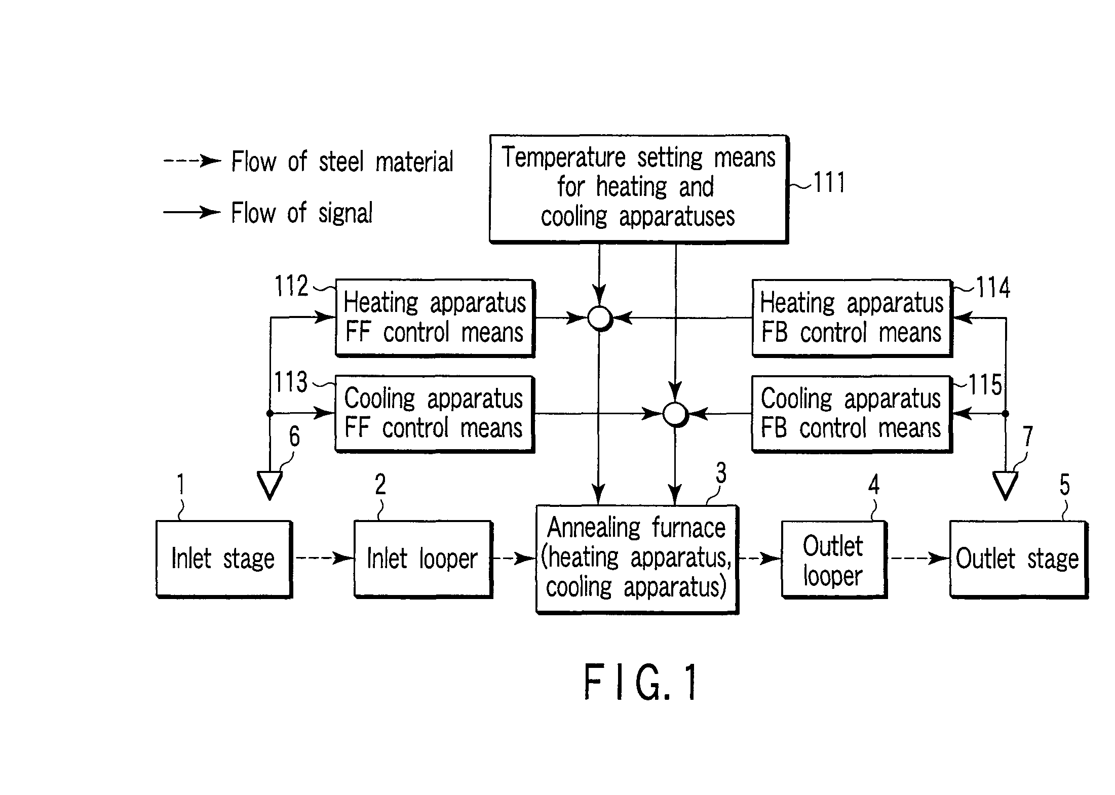
[0041]FIG. 1 is a block diagram illustrating a first embodiment in accordance with the present invention. As described above, the CAL is composed of roughly five stages, an inlet stage 1, an inlet looper 2, an annealing furnace (hereinafter simply referred to as a furnace) 3, an outlet looper 4, and an outlet stage 5. The furnace 3 is composed of a heating apparatus and a cooling apparatus, the heating apparatus being located upstream of the cooling apparatus. However, depending on a set temperature for each section in the furnace 3, the cooling apparatus may be a temperature holding apparatus. For the set temperature for each section in the furnace 3, temperature setting means 111 for the heating and cooling apparatuses preset, for example, temperature set values of 800° C. for the heating apparatus and 300° C. for the cooling apparatus.

[0042]Material quality measuring apparatuses 6, 7 described below are arranged in the inlet stage 1 and the outlet stage 5, respectively. Specifica...

second embodiment

[0093]FIG. 7 is a block diagram illustrating a second embodiment in accordance with the present invention. FIG. 7 differs from FIG. 1 in that the single furnace 3 is divided into a furnace 3a having a heating apparatus and a furnace 3b having a cooling apparatus, with a material quality measuring apparatus 8 installed in the divided portion, specifically at an appropriate position between the soaking section 33 and the cooling section (1)34, shown in FIG. 6, so as to allow the temperatures of the heating and cooling apparatuses in the furnaces to be controlled as follows. Specifically, the material quality measuring apparatus 8 measures the quality of the steel material. On the basis of the measurement results for the quality of the steel material, corrections are made of the temperatures of the heating apparatus (intermediate control means) 116 in the furnace 3a and the cooling apparatus (intermediate control means) 117 in the furnace 3b.

[0094]The second embodiment configured as d...

third embodiment

[0095]FIG. 8 is a block diagram illustrating a third embodiment in accordance with the present invention.

[0096]Speed setting means 118 sets the conveyance speed for the steel material in the furnace 3 at a set value of, for example, 10 m / s.

[0097]The material quality measuring apparatuses 6, 7 are arranged in the inlet stage 1 and outlet stage 5, respectively. Measurements are made of the quality of the steel material, specifically, the crystal grain size and r value of the steel material before the material is carried into the furnace 3 and while the material is being carried out of the furnace 3.

[0098]A measurement result from the material quality measuring apparatuses 6 is input to heating apparatus feed-forward (FF) control means 122. On the basis of the measurement result from the material quality measuring apparatus 6, the heating apparatus feed-forward (FF) control 122 means determines that it is proper to set the conveyance speed for the steel material in the furnace 3 at, fo...


PUM

PropertyMeasurementUnit
speedaaaaaaaaaa
temperatureaaaaaaaaaa

Abstract

A process line control apparatus which controls a process line including an annealing furnace (3) including a heating process apparatus executing a heating process and a cooling process apparatus executing a cooling process, the heating and cooling processes being continuously executed on a steel material, the apparatus having feed forward control means (112, 113) for measuring quality of the steel material by a material quality measuring apparatus (6) installed in an inlet stage (1) preceding the heating process in the annealing furnace (3), and on the basis of measurement results, determining modifications for respective temperature set values set by temperature setting means (111) for the heating and cooling apparatuses in the annealing furnace (3), and feedback control means (114, 115) for measuring the quality of the steel material by a material quality measuring apparatus (7) installed in an outlet stage (5) succeeding the cooling process in the annealing furnace (3), and on the basis of measurement results, determining modifications for the respective temperature set values set by the temperature setting means (111) for the heating and cooling apparatuses in the annealing furnace (3).

Description

TECHNICAL FIELD[0001]The present invention relates to an apparatus and method for controlling a process line such as a continuous annealing line or a plating line in which steel materials are continuously processed.BACKGROUND ART[0002]In general, in a line called a process line, annealing or plating is performed on steel materials. The annealing is a process of heating a cold-rolled and hardened steel material to about 700 to 900° C. for softening so that the steel material can be easily processed during a postprocess. In this case, the heating allows iron atoms to move easily, recovering and recrystallizing steel crystals hardened by the processing. New crystal grains of a size corresponding heating and temperature maintenance conditions are generated and grown.[0003]A conventional technique places a coil directly into a box-shaped furnace for annealing (this is called batch annealing). However, in recent years, a continuous annealing line (CAL) for continuous annealing has often b...

Claims


Application Information

Patent Timeline
Patent Type & Authority Applications(United States)
IPC IPC(8): C21D11/00
CPCC21D1/26C21D9/56C21D9/562F27D19/00C21D11/00C21D11/005C23C2/003C21D9/573
Inventor IMANARI, HIROYUKISANO, MITSUHIKOOHARA, KAZUHIRO
Owner TOSHIBA MITSUBISHI-ELECTRIC IND SYST CORP
Why Eureka
Try Eureka