
Electric power supplying apparatus and electric power transmitting system using the same

a technology of electric power transmission system and electric power supply apparatus, which is applied in the direction of near-field systems using receivers, resonant antennas, inductances, etc., can solve the problems and achieve the effect of reducing the transmission efficiency of electric power

Inactive Publication Date: 2010-09-02
SONY CORP
View PDF8 Cites 180 Cited by
  • Summary
  • Abstract
  • Description
  • Claims
  • Application Information

AI Technical Summary

Benefits of technology

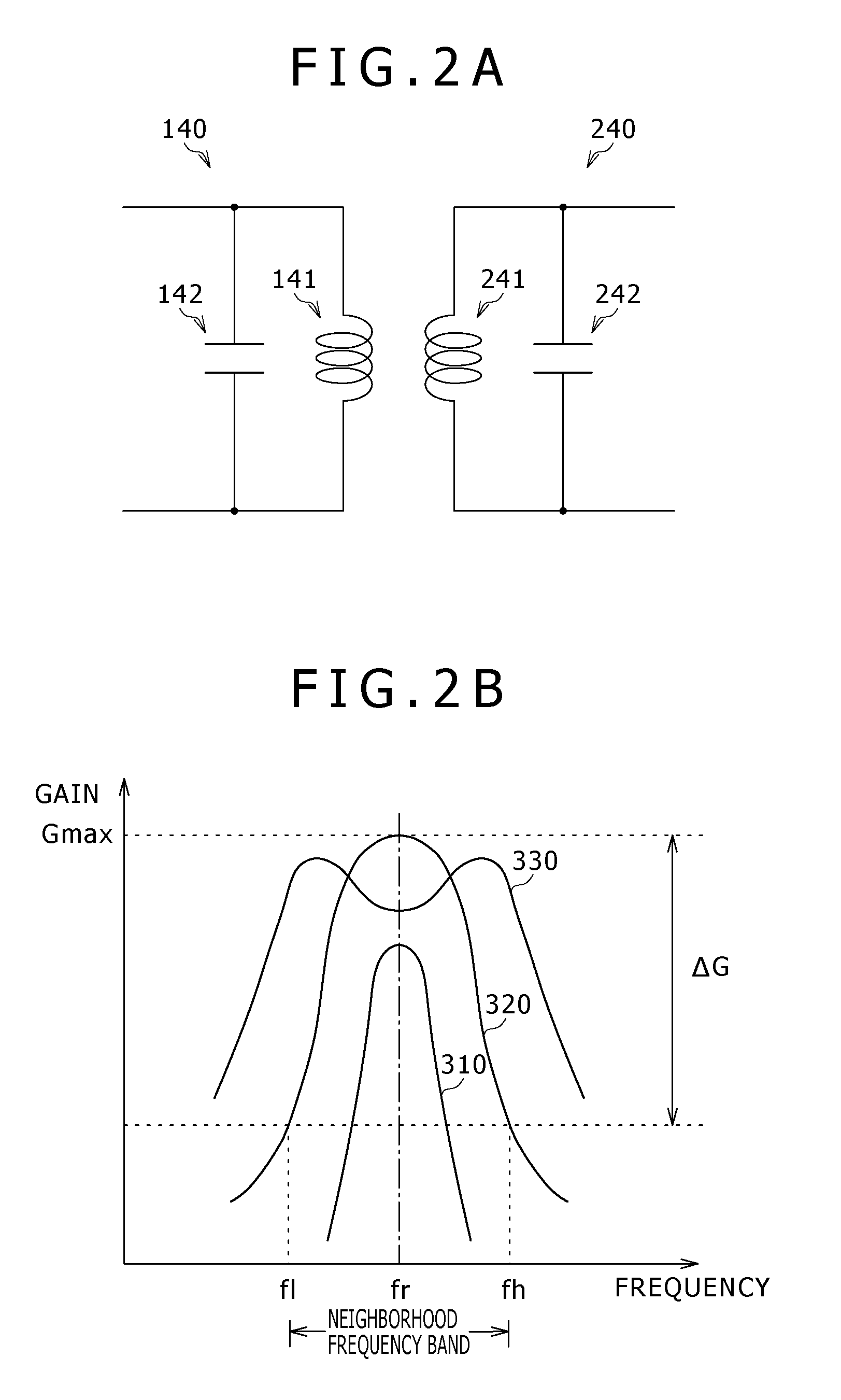
[0006]For this reason, when the electric power is transmitted by setting a frequency of an electric signal supplied to the resonance circuit at a frequency corresponding to the maximum gain of the single peak characteristics, there is caused a problem such that when the distance between the resonance circuits becomes too short, the transmission efficiency of the electric power is reduced.
[0014]As set forth hereinabove, according to the present invention, it is possible to offer the superior effect that the reduction of the transmission efficiency of the electric power in the tight coupling state between the resonance circuits.

Problems solved by technology

For this reason, when the electric power is transmitted by setting a frequency of an electric signal supplied to the resonance circuit at a frequency corresponding to the maximum gain of the single peak characteristics, there is caused a problem such that when the distance between the resonance circuits becomes too short, the transmission efficiency of the electric power is reduced.

Method used


Image

  • Electric power supplying apparatus and electric power transmitting system using the same
  • Electric power supplying apparatus and electric power transmitting system using the same
  • Electric power supplying apparatus and electric power transmitting system using the same

Examples


first embodiment

1. First Embodiment

Configuration of Electric Power Transmitting System

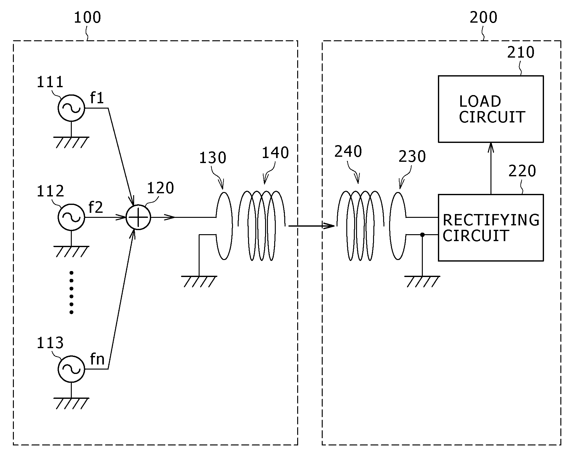
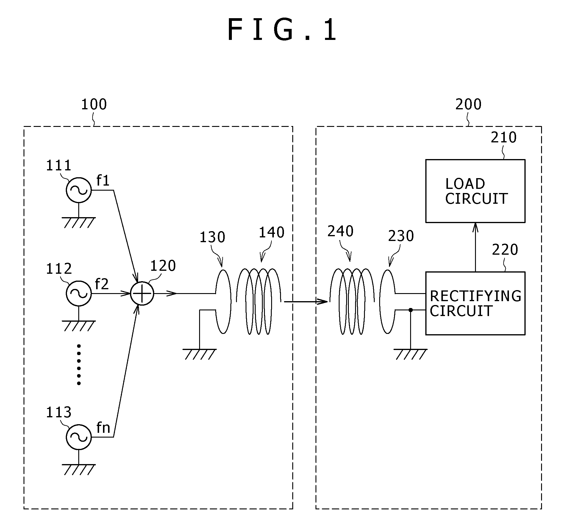
[0027]FIG. 1 is a block diagram, partly in circuit, showing a configuration of an electric power transmitting system according to a first embodiment of the present invention. This electric power transmitting system includes an electric power supplying apparatus 100 and an electric power receiving apparatus 200. Here, the electric power supplying apparatus 100 supplies an electric power by using coupling caused by a magnetic field resonance. Also, the electric power receiving apparatus 200 receives the electric power from the electric power supplying apparatus 100. In this case, a movable body such as a robot which moves to an arbitrary place by receiving electric power from the electric power supplying apparatus 100 is supposed as the electric power receiving apparatus 200. For this reason, a distance between the electric power supplying apparatus 100 and the electric power receiving apparatus 200 in the electric ...

second embodiment

2. Second Embodiment

Configuration of Electric Power Transmitting System

[0060]FIG. 4 is a block diagram, partly in circuit, showing a configuration of an electric power transmitting system according to a second embodiment of the present invention. This electric power transmitting system includes the electric power supplying apparatus 100 and the electric power receiving apparatus 200 similarly to the case of the electric power transmitting system of the first embodiment. The electric power supplying apparatus 100 includes a communicating portion 170 and a frequency generator controlling portion 180 in addition to the constituent elements of the electric power supplying apparatus 100 of the first embodiment shown in FIG. 1. In addition, the electric power receiving apparatus 200 includes a spectrum analyzing portion 250, a frequency information creating portion 260, and a communicating portion 270 in addition to the constituent elements of the electric power receiving apparatus 200 of...


PUM


Abstract

Disclosed herein is an electric power supplying apparatus, including: a resonance circuit having an inductance and a capacitance; and an electric power synthesizing circuit configured to synthesize electric powers of electric signals composed of a plurality of frequency components in a neighborhood frequency band as a frequency band near a resonance frequency decided by the inductance and the capacitance with one another, and output a resulting electric signal obtained through the electric power synthesis to the resonance circuit.

Description

BACKGROUND OF THE INVENTION[0001]1. Field of the Invention[0002]The present invention relates to an electric power transmitting system, and more particularly to an electric power supplying apparatus for supplying an electric power by using a magnetic field resonance, and an electric power transmitting system using the same.[0003]2. Description of the Related Art[0004]Heretofore, a technique utilizing an electromagnetic induction has been widely used as an electric power transmitting technique utilized on a wireless basis. On the other hand, in recent years, an electric power transmitting technique utilizing a resonance of either an electric field or a magnetic field has attracted attention. For example, there is proposed an electric power transmitting system using a resonance phenomenon of a magnetic field generated by a resonance circuit composed of a coil and a capacitor. This electric power transmitting system, for example, is disclosed in U.S. Patent Application Publication No. ...

Claims


Application Information

Patent Timeline
IPC IPC(8): H02J17/00H04B5/02
CPCH02J5/005H01Q9/04H02J50/80H02J50/12
Inventor KOMIYAMA, SHINJIFUJIMAKI, KENICHIMITA, HIROYUKI
Owner SONY CORP
Learn More